Successful LinuxCNC Stepper Motor Test

Setting up an old PC to explore LinuxCNC was pretty easy. I had most of the hardware sitting around, the only thing I had to buy was a PCIe parallel board built around a MCS9900 chip which I chose for its LinuxCNC support. The next step is to connect it to some mechanical hardware to see if it even works. In order to do that, I had to find the physical addresses assigned to the parallel port card. I’ve been playing around with PC hardware long enough to remember add-on cards that required fussing with jumpers to set hardware addresses, but that hasn’t been necessary for decades. PCIe cards are assigned their resources automatically and modern software had ways to enumerate and find those values. For LinuxCNC we had the first part — automatic assignment without jumpers or such — but for whatever reason we do not have the second part.

PCie NetMos 9900 parallel controller at e010

Instead of LinuxCNC automatically finding the parallel card and figuring out what to do with it, the setup person has to run Linux command line utilities to find these numbers and write them down for input to LinuxCNC later.

The next task is to find an old school parallel cable. This was surprisingly difficult in this day and age. Every longtime PC user would claim they have several in a box somewhere, but unable to find the right box because it’s been so long.

Parallel cable beheaded

Eventually one was found so I could cut it up to access wires within. I just need two signal wires (plus ground wire) for the first test, driving “step” and “direction” control signals of a motor controller.

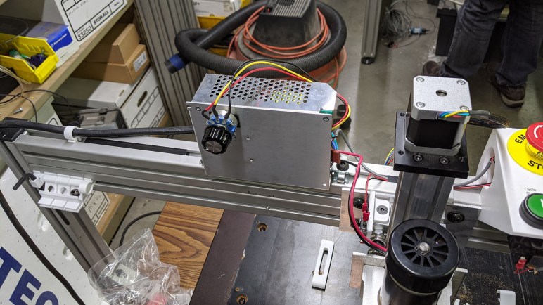
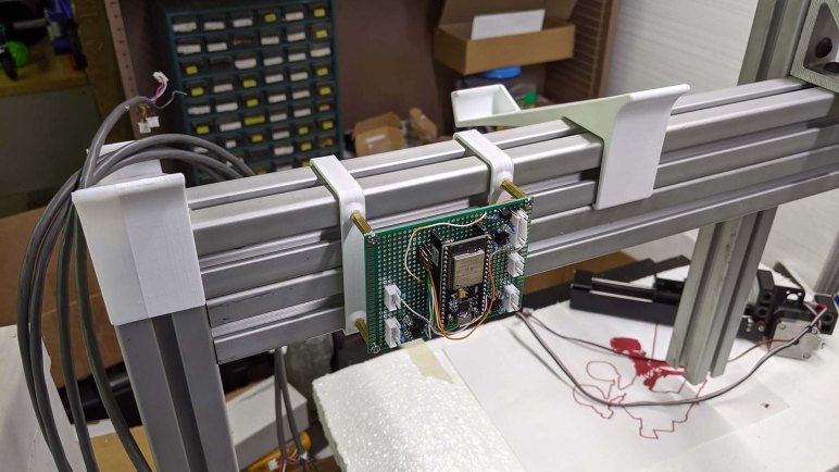
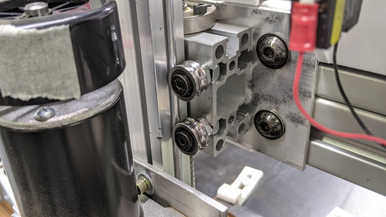
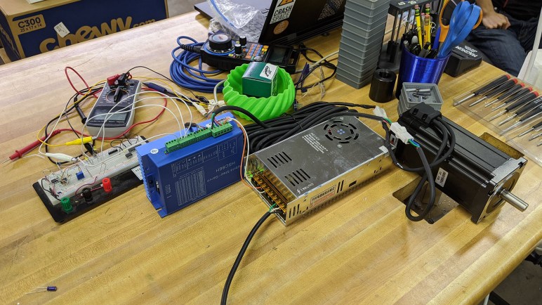
The motor hardware visible here was a hybrid stepper motor system(*) that was sitting on a shelf and available for experimentation. The “hybrid” in this case meant something that could accept step/direction commands like a stepper motor, but unlike normal stepper motors this system has a closed-loop feedback system. Normal stepper motors are open-loop, meaning they just go through their motions but have no idea what the motor output shaft is actually doing. It might miss a step or two and the system wouldn’t know. This hybrid system includes a motor shaft position encoder, so it knows when a step is missed and can compensate. Such systems are more expensive but allows more efficient operation (use just enough electric power to deliver commanded steps) and more usable power (don’t need to allocate as much to error margin.)

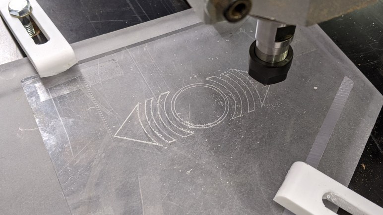
This successful was completely within the LinuxCNC stepper motor configuration wizard and its “Test Axis” button. It established step/direction works as expected, and that acceleration/deceleration curves are smooth in practice. But this is very far from running a G-Code program in LinuxCNC. It doesn’t tell me if multiple axes will coordinate successfully in multi-axis motion, and it is far too short in duration to prove long-term reliability. Still, it’s a good start, and I’m a little sad I didn’t get to go further.

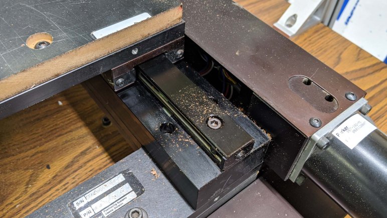
We had our pandemic lockdown shortly after this milestone. The workspace where I had been working on this homebrew CNC project was no longer available. I got my LinuxCNC PC back, but the hybrid stepper motor is now out of reach. I was given the Parker XY stage itself (including the two driver boxes) and the spindle I bought, but the rest of the gantry test system was disassembled and returned to their respective owners. I hope to resurrect this project at some point, but its future is uncertain.


(*) Disclosure: As an Amazon Associate I earn from qualifying purchases.

PCI Express Parallel Port Card for LinuxCNC

While putting together a PC to investigate LinuxCNC, I installed a wireless networking card that turned out to be unsupported. I was able to shrug that off as unimportant, but that would not be true of the next hardware project: adding a parallel port to the machine. Parallel ports have been around for as long as the PC platform has been around and is the closest thing a PC has to GPIO pins. (Actually, mostly just output.) There are many fancier options with add-on cards with programmable FPGA and such, but they all boil down to low-latency output signal pins and parallel port is the pioneer for all that followed.

The starting point for this investigation is the LinuxCNC wiki for parallel port cards. I would not have been surprised if they focused on ISA cards of the original IBM PC, but fortunately they aren’t quite that old school which is good. Most of the entries talk about far more modern PCI cards. As I understand it, something using the MCS9865 chip (*) is the gold standard, preferably a dual port version for double the pins. There are other pages written by people reporting good results, but many (like this page about Netmos 9815) are out of date and no longer available.

Unfortunately, the only expansion slot on this MSI AM1I Mini-ITX is a single PCI-Express (PCIe) slot intended for a GPU. Though handled by the same industry consortium, PCI and PCI-Express cards have physically incompatible shapes. I went to Amazon looking for PCI-Express parallel cards that explicitly mention Linux CNC. Thanks to the similar name, Amazon would show PCI (non-express) cards which I can’t use. And for reasons I don’t understand, some USB adapters were shown(*) even though they would not work for this purpose: USB adds an unpredictable latency unacceptable for direct machine control.

Another tack I tried is to search for LinuxCNC wiki for parallel port chip identifiers. AX99100 came up empty. WCH382L boards are available (*) but they have been problematic and no longer recommended. OXPCIe952 boards are available (*) and LinuxCNC support for this chip has apparently matured past an early problematic teething period. Out of chips found on PCIe boards, the MCS9900 appears to have the longest track record. So I decided to try this unit (*) as my starting point.

PCIe parallel port card installed

The interface card itself installed easily, just like countless other PC add-on cards I’ve installed. The real proof requires connecting it to some mechanical hardware.


(*) Disclosure: As an Amazon Associate I earn from qualifying purchases.

LinuxCNC has Limited Hardware Support: Wireless Card Example

An important part of my home-built CNC project is to learn more about what goes on under the hood of CNC equipment, arguably more interesting to me than actually getting a machine up and running doing something productive. Which is why I decided against buying an all-in-one CNC control system and started putting together a machine to play with LinuxCNC instead. I was surprised to learn conventional wisdom for LinuxCNC has a preference for older machines. Steady and predictable is better than infrequent bursts of high performance. Modern PCs tend to be optimized for the latter.

Another reason is hardware support. While LinuxCNC is indeed built on a Linux kernel, there is little motivation to adopt the latest and greatest Linux features. LinuxCNC aims for steady reliable machines, which means avoiding new features if they might make machines less reliable. Older code means support for older hardware, and fewer hardware. Something that runs on a modern commodity Linux distribution has no guarantee LinuxCNC cares about it. I learned this lesson up front with a wireless card.

The motherboard I chose to use for LinuxCNC exploration is the MSI AM1I board that had been the heart of my home FreeNAS (now TrueNAS) server for several years before being decommissioned. It is the oldest PC motherboard I have right now, and it has a proven history of reliability. While I had the motherboard accessible for installation in a steel tower case, I thought I’d add wireless Ethernet capability to the system. This motherboard has a Mini-PCIe slot intended for a wireless card, and I had salvaged an appropriately sized card from a retired laptop.

Intel wireless-N 1030 card installed

It installed easily.

Intel wireless-N 1030 card antenna

I had also salvaged two antenna that had connected to this card. In the laptop, the wires were routed through screen hinge to connect to these antennae sitting within upper left and right corners of the screen. Now I shall route them to a plastic faceplate covering for an absent optical drive.

This was a widely supported Intel wireless card that had worked in the laptop (before it died) and still worked when I booted Ubuntu on this computer. LinuxCNC recognized it as a piece of hardware on the PCIe bus, but there was no networking connectivity. I had a wired Ethernet backup option readily available, so I didn’t spend time diagnosing how to connect to a network with this hardware. I’ve learned my lesson and put more research into the next piece of hardware: a PCI-Express Parallel port card.

Window Shopping RATTMMOTOR CNC Controller with Digital Dream

I determined that a Mach 3 CNC pendant wasn’t going to work in LinuxCNC with merely configuration file changes, so I started looking at other pendant options. I found this bare-bones option(*) that had only a few controls and no display screen, and almost every single function is broken out into its own physical wire. This fits very well with the LinuxCNC model built on the idea every I/O is a pin. Even when it’s not literally a pin on a parallel port, there’s a logical pin underneath for LinuxCNC configuration.

And while looking at these pendants designed for hard wiring, I found a controller that bundles such a pendant with a complete self-contained CNC controller unit. It is more capable than Grbl on an Arduino, but less than full LinuxCNC on a PC. It calls itself an offline motion controller system(*), running software from Digital Dream Automation. At a quoted maximum pulse rate of 500 kHz, it significantly outperforms Arduino Grbl which is reported to top out at around 30 kHz. This unit can also read G-Code from a USB flash drive, eliminating the need to have a separate computer running some sort of G-Code sender program to Grbl. A nice self-contained (I guess that’s what they meant by “offline”?) system.

Minor problem: G-code visualization options on such a little screen seems to be limited to 2D plots, giving up one of three axes. I’ve seen old CNC with the same limitation so it’s not a huge deal, but it is less than what we can do with modern PC-based systems.

Moderate problem: How would I generate G-code for these units? This particular unit’s owner’s manual explains firmware updates would be downloaded from ddcnc.com, and that’s how I found Digital Dream and presumably they are the author of software running on these units. Unfortunately, a quick search for Digital Dream on Fusion 360 post processor library came up empty. I don’t know how owners of DDCNC-based controllers like this one generates their G-code programs. The user manual has a list of supported commands, but I’m not familiar enough with the various styles to recognize if DDCNC uses the same set of code as something else.

Major problem: Buying such a product instead of setting up LinuxCNC comes with a drawback: I can’t dig into the code and learn how CNC controllers work under the hood. And that is the primary point of my CNC controller explorations. If someone asks me for a ready-made upgrade over Grbl on Arduino or ESP32, I’m happy to let them know these controllers exist. But for myself, I’ll resume my LinuxCNC explorations.


(*) Disclosure: As an Amazon Associate I earn from qualifying purchases.

Brief Look at a LinuxCNC Pendant

Trying to build a little CNC is definitely a learn-as-I-go project. Moving the motor control box was a simple (though necessary) mechanical change, but not the only idea prompted by initial test runs. I also thought it would be nice to have a handheld pendant to help with machine setup, instead of going to the laptop all the time. I got a chance to look over a CNC pendant to see how I might integrate one.

This particular unit was purchased from this eBay vendor listing, but there are many other similar listings across different online marketplaces. Judging by this listing’s title, the popular keyword salad included: CNC Mach3 USB MPG Pendant Handwheel. I knew what CNC, USB, pendant and handwheel referred to. MPG in this context means “Manual Pulse Generator” referring to the handwheel that generates pulses to signal the CNC controller to move individual steps. And finally, Mach3 is a Windows software package that turns a PC into CNC machine controller.

My first draft CNC controller was built on an ESP32 without USB host capability, so there’s little hope of integrating this USB pendant. The most likely path would involve LinuxCNC, a freeware alternative to Mach3. Poking around documentation for control pendants, the first hit was this link which seems to be talking about units that connected via parallel port. Follow-up searches kept coming across this link for wireless pendants which I didn’t think was relevant. After coming across it for the fifth or sixth time, I decided to skim the page and saw that it also included information about a wired USB pendant. It’s not a direct match, though. Here’s information from Ubuntu’s dmesg tool after I plugged in this pendant.

[ 218.491640] usb 1-1: new full-speed USB device number 2 using xhci_hcd
[ 218.524920] usb 1-1: New USB device found, idVendor=10ce, idProduct=eb93
[ 218.524926] usb 1-1: New USB device strings: Mfr=1, Product=0, SerialNumber=0
[ 218.524931] usb 1-1: Manufacturer: KTURT.LTD
[ 218.538131] generic-usb 0003:10CE:EB93.0004: hiddev0,hidraw3: USB HID v1.10 Device [KTURT.LTD] on usb-0000:00:10.0-1/input0

The key here are USB identifiers idVendor and idProduct, 0x10CE and 0xEB93. I could change those values in the associated udev rule:

ATTRS{idVendor}=="10ce", ATTRS{idProduct}=="eb93", MODE="666", OWNER="root", GROUP="users"

But that was not enough. I dug deeper to find relevant source code and it is explicitly looking for idVendor:idProduct of 0x10CE:0xEB70.

dev_handle = libusb_open_device_with_vid_pid(ctx, 0x10CE, 0xEB70);

Oh well, getting this to run would go beyond just configuration files, there will need to be code changes and recompiles. Looks like some people are already looking at it, a search for eb93 found this thread. I don’t know enough LinuxCNC to contribute or even understand what they are talking about. I returned this USB pendant to its owner and set this idea aside. There are plenty of CNC pendant offerings out there I can revisit later, some of which are even bundled with an entire CNC control package.

Moving CNC Spindle Control To Equipment Panel

Thinking about CNC milling circuit boards might have been looking too far ahead. But I also made some mechanical changes after the successful engraving session. There was a distinct buzzing sound of vibration caught my attention. Unlike earlier tests with an endmill, this engraving tip removed very little material and I thought overall noise would be reduced. Most of it were, but one particular sound stayed the same and I wanted to know what it was.

A little bit of investigation found the source of the buzz inside my spindle motor controller box. Bolted near the spindle up on our Z-axis gantry beam, it was installed in that location purely out of convenience. A decision that was apparently not well thought out and contributing to headaches. Earlier we found the box had contributed electrical noise to the system, now I realized it contributed mechanical noise as well.

In addition to those problems, its current position also blocked the most promising path for us to install a dust collection system. And even if it was not directly blocking, we wouldn’t want it to be near dust path anyway.

All of those factors motivated a move from its current gantry-mounted position down below decks to the equipment plate where the Parker motion control X/Y stepper driver modules are mounted. In additional to longer wiring to cover the distance, a few other enhancements were made. We had a single capacitor installed on the motor wire to help our previous episode of electrical noise. Now the wire is longer and even more likely to turn into an antenna, so now we have one capacitor at each end. There’s a ferrite core added to each end as well, and the ground wire is now bolted to the equipment panel plate. All of these should give us better electrical noise resistance than before.

In addition to the motor wire, I extend wire connecting enable pin to E-stop so spindle power is cut when E-stop is pressed. I also extended the control wire for speed. Automated operation would require automatic speed control via Grbl, but this will do until I get around to it.

Spindle control mounted below

Side amusement: since this project involved mains voltage, I unplugged this box before moving and rewiring it. Then I immediately forgot I had unplugged it.

Once I plugged it back in, things started running as expected. This is a small step forward, something I like to interleave with investigations looking further ahead.

Circuit Board Milling Fixture First Draft

My short daydream about hobbyist-level tool-changing CNC was associated with the project to build a CNC from a 2-axis motion-controlled optical inspection table. Shortly before pandemic lockdown it reached the milestone of engraving a scrap sheet of polycarbonate plastic (“Lexan”). A lot of things have changed since then, putting the project in limbo, but I have a few partially written entries languishing in my “Drafts” folder. Following the precedence set by that tool-changer post, I intend to do a bit of polish and publish them for the record. First up: an idea for milling custom PCBs on the machine.

After that successful engraving test, I started considering PCB milling. It is another largely 2D task with tighter precision requirements than engraving cosmetic details, without increasing requirements on physical side loads and machine rigidity. I bought a batch of single-sided copper-clad boards (*) and started thinking about how I might design a fixture to mill them. This was the first draft, which I never got to test.

The idea was to create a small 3D-printed object that I could bolt to the MDF working surface of my XY Stage CNC. The object’s top surface is intended to be milled after bolting in place, to make sure it is flat/parallel with machine motion axis. The side overhangs are designed for 3D-printed clips that will hold the board in place while milling.

The first draft of the clips had very little holding power, because I anticipated physical forces would act a certain way and reality worked differently than how I thought. I had curved it so it clamps to the top surface as well as the rail, but doing so meant less force on the actual PCB holding claw.

The second draft was more successful, the PCB holding claw became part of the topside holding force. I also extended the shape downwards so it could brace against an additional surface for more strength.

PCB milling fixture installed

The idea was to put double-sided tape on the board’s back side before sticking it on this fixture. The clips would then exert downwards force on the double-sided tape to improve its resistance to sideways cutting forces. Would the tape add too much variation to the height? Would it flex too much for accurate cutting? Would the clips help or hinder the operation? I fully expected this first draft to not work as expected but looked forward to learning exactly how. Once this prototype fixture was bolted to the surface, I started looking into using FlatCAM to generate PCB-milling G-code. I never got far enough for a test run but I did make some mechanical refinements.


(*) Disclosure: As an Amazon Associate I earn from qualifying purchases.

Hobbyist Level CNC Tool Change Support (M6)

In our experiments so far, the project CNC machine used Bart Dring’s ESP32 port of Grbl to translate G-code into stepper motor step+direction control pulses. It offers a lot of neat upgrades over standard Grbl running on an Arduino, and both are fantastically affordable way to get into CNC. The main issue with Grbl running on microcontrollers is the fact they are always limited by the number of input/output pins available. Some of Bart Dring’s ESP32 enhancements were only possible because the ESP32 had more pins than an ATmega328.

But like all tinkerers, we crave more. Grbl (& derivatives) are understandably lacking support for features that are absent from majority of hobbyist grade CNC. The wish list items in the local maker group mostly center around the capability to use multiple tools in a single program.

Tool change is the most obvious one. Grbl recognizes just enough to support a manual tool change operation: stop the spindle, move to a preset tool change position, and wait before proceeding. Automated tool changing is out of scope.

Which explains the next gap in functionality: tool length offset. Not all tools are of the same length and the controller needs to know each tool length to interpret G-code correctly. Grbl doesn’t seem to have a tool length table to track this information. It is a critically important feature to make automated tool change useful, but the lack of latter means the lack of former is not surprising.

And following the cascade of features, we’d also love to have cutter radius compensation for individual tools. Typically used in industrial machinery to gradually adjust for tool wear, it usually doesn’t matter in the type of tolerances involved in the context of hobbyist machines. But it is useful and nice to have if multiple tools come into the picture, each with their own individual idiosyncracies.

These capabilities get into the domain of industrial controllers well beyond a hobbyist budget. Or at least, they used to be. People are experimenting with hardware builds to implement their own automatic tool changing solutions. And on the software side, Grbl derivatives like GrblHAL have added support for the M6 (automatic tool change) code allowing multiple tools in a single CNC program. Is it a practical short-term goal for my project? Heck no! I can’t even cut anything reliably yet. But it’s nice to know the ecosystem is coming together to make hobbyist level tool-changing CNC practical. It’d be useful for a wide variety of CNC tasks, including routing vs. drilling operations for milling circuit boards.

Successful Polycarbonate Plastic Engraving Session

The first test run for CNC engraving was done on a piece of MDF. Mainly because the piece was already in the machine, surfaced, and ready to go. It was also a forgiving material in case of mistakes, but MDF doesn’t show engraved details very well.

The next session increased the difficulty level: now we have a piece of scrap polycarbonate plastic (“Lexan”) for our next engraving test. This material is interesting because it has different properties than PMMA (a.k.a. acrylic.) The latter is a popular material for laser cutting but also very brittle, very vulnerable to cracking under stress. Polycarbonate plastics are much more robust and a better choice when physical strength is important in a project.

Acrylic is also popular for laser engraving projects, but polycarbonates do not engrave or cut easily under laser power due to its different properties. It is not particularly friendly to CNC machining, either, but we’ll start with an engraving project before we contemplate milling them.

Thankfully the first session was a success, and illustrates some of the challenges of working with such materials. The toughness of the material also meant the little strings of cut chips want to remain attached to the stock, making cleanup a hassle. Upon close examination, we saw the engraved groove is slightly deeper on the left side than the right. Proof our scrap MDF working surface is not flat which was not a surprise, but “flat enough” within 4-8 thousands of an inch (1-2 sheets of normal office paper) which was better than expected.

Even with its imperfections, performance on this test indicates the machine is capable of engraving on materials we can’t use in the laser cutter. That might be useful, and a good example of how we can still learn lessons on this machine despite its flawed Z-axis and other problems. We should still fix them, of course, but the machine can already be useful while we work on those improvements.

A Vortex (or Cyclone) Separator Appears

After each of the test cut runs on our project CNC, I’ve used the shop vacuum to clean up the mess afterwards. However, this does not help with the mess during cutting, the most important part of which are our machine’s ways and drive screws which are vulnerable from debris. What we really need is some kind of collection system that we can run while the machine is cutting.

One problem with this requirement is the fact that vacuum filters quickly clog up when used in this manner. The standard solution is to separate bulk of debris from the airflow before it flows into the filter, thereby extending life of the filter by reducing the amount of debris it has to catch out of the air. Since this is a standard solution, many products are available for purchase. But being makers, our first thought was how we might make one for less money, and 3D printing seemed like a way to go. Since the device is mainly a hollow shell, in theory we could print one for less money in plastic filament than buying one.

However, the problem is that none of my 3D printers are well suited to printing a tall cylindrical object exceeding my printer volume. And if I should split it across several pieces, I risk introducing a gap that can compromise the vacuum and also disrupt the debris extraction airflow. This type of project is ideally suited for a tall delta-style 3D printer, so I started asking around fellow makers of SGVHAK if anyone had one of those printers.

One member did have such a printer, and asked what I wanted to print. When I described the project, he suggested that we skip the printing. Some time ago he purchased a vortex separator (*) for another project, and it is now available for this project CNC. I agree taking a manufactured unit is much easier than printing one! It is even a perfect fit with the nature of our project, which is mostly built from parts salvaged or recycled from earlier projects.

But the vortex separator is only a single core component, we’ll have to build the rest of the dust collection system.


(*) Disclosure: As an Amazon Associate I earn from qualifying purchases.

Contamination Concern for CNC Ways And Drive Screw

Thinking over potential tasks to be tackled on our project CNC, we thought it might be occasionally useful to mill our own circuit boards. But before we start cutting bits of copper off fiberglass, we should make sure those flakes of copper won’t end up where they’ll do harm. One of the open questions involves how we should protect the ways and drive screws of our Parker motion control XY stage.

The XY stage was salvaged from an optical inspection machine, so it was not a surprise to see this mechanism has limited protection against contamination as most items under optical inspection don’t shed debris. Hence unlike real CNC mills, the ways here have no cover. On this machine they are exposed when an axis moves off center. Cursory inspection indicates the critical surfaces are those in the center facing to the side, so what we see as top surfaces are not areas of direct contact. But it’s still better to not have any contaminants build up here, because of the next item:

The drive screws have a thin metal cover to protect against dust, but the cover is opened towards the ways. When the table moves off center, there is a window for debris to fall from exposed ways to inside the screw compartment and end up sticking to the lubricant coating the mechanism. In the picture above we could see through this hole. While the screw itself is dark and out of line of sight, we could see colors of wires also living in that compartment. (They connect to three magnetic switches for the axis: a location/homing switch, and limit switches to either extreme.)

We realized this would be a problem once we started cutting into MDF and making a big mess. Powdered MDF may cause abrasion and should be kept out of the ways and screws if we can. Milling circuit boards would generate some shredded copper. I’m not sure if that would be considered abrasive, but they are definitely conductive and we should keep them away from machine internals as much as possible. A subtractive manufacturing machine like this one will always make big messes, how might we keep that under control?

Contemplating CNC Milling Circuit Boards

Another activity that we will be investigating in addition to CNC engraving is the potential of making our own circuit boards. Mechanically speaking, milling circuit boards are very similar to engraving. Both types of tasks stay within a very shallow range of Z, and would suffer little impact by our wobbly Z axis. Milling boards could involve larger tools than a pointy engraving tool, but they should still be relatively small and not drastically strain our limited gantry rigidity.

Experimentation will start with the cheapest option: blank circuit boards that have a layer of copper on one side. (“single-sided copper clad”) This will be suitable for small projects with a few simple connections that we had previously tackled with premade perforated board and some wires. For example, Sawppy’s handheld controller could have easily been a single-layer board. We would need to go to dual layer for more sophisticated projects like the Death Clock controller board, and the ambition for this line of investigation is for the machine to make a replacement control circuit board for itself.

We don’t yet know how feasible that will be. As the level of complexity increases, at some point it won’t be worth trying to do board ourselves and we’re better off sending the job to a professional shop like OSH Park. And the first few boards are expected to be indicative of amateur hour and a disaster, hence we didn’t care very much about the quality of the initial batch of test boards. They were purchased from that day’s lowest bidder and second lowest bidder on Amazon. (*)

But even though circuit board milling is mechanically similar to engraving, the software side is an entirely different beast that will need some ramp-up time. And before we start cutting metal in the form of a thin layer of copper, we need to pay some attention to the machine’s needs.


(*) Disclosure: As an Amazon Associate I earn from qualifying purchases.

Comparing CNC Engraving Tool To Milling Tool

The decision to explore CNC engraving was so we can learn machine tool operation while sidestepping the weaknesses currently present in our project CNC machine. Projects staying within a single Z depth will suffer minimally from the Z-axis wobble imparted by our bent Z-axis ballscrew. But engraving also helps reduce impact from the lack of rigidity due to differences in our cutting tools.

CNC with cutter 80mm past motor bearing

Here’s the 1/4″ diameter endmill as it was installed in our CNC spindle. In the pursuit of rigidity I wanted the largest diameter that we can put in a ER11 collet not realizing the large diameter also meant longer length. I bought this one solely because it could be available quickly but a more detailed search found no shorter cutters. The end of this particular cutting tool extends roughly 80mm beyond the spindle motor bearing.

In comparison, the engraving tool had a 1/8″ diameter. Judging just by diameter, the 1/8″ diameter tool would be weaker. But that overlooks the fact it is also shorter, resulting in its tip extending only about 55mm beyond the spindle motor bearing. So not only is the engraving bit removing less material and placing less stress on the spindle as a result, it also has a 30% shorter leverage arm to twist the Z-axis assembly about.

Now I understand why such simple inexpensive mills and small diameter tools are a common part of modest desktop CNC mills. (*) The load imparted by such a Z-axis assembly is very modest, making it possible to have machines that are barely any more rigid than a 3D printer. (And in some cases, not even as rigid.) While our Parker XY table is far more capable than the XY stage in these machines, our Z-axis isn’t much better (yet) so we’ll stay in a similar arena low lateral load and material removal.


(*) Disclosure: As an Amazon Associate I earn from qualifying purchases.

CNC Exploration Via Flat Cutting Projects

We got far enough on the project CNC mill (built out of mostly salvaged parts) to make test cuts, and evaluate results. I honestly didn’t think we would get this far. Back when I first plugged in the salvaged Parker motion control XY table I had only a vague clue where I might go with it, only knowing that I will be learning a lot as I go. Now here’s a machine capable of making a decent effort executing G-code programs generated from Autodesk Fusion 360.

There was never a real solid goal for this project, no “North Star” to guide the direction nor a finish line to mark completion. I think I can now articulate the underlying goal for this project: to learn as much as I can about the world of automated machine tools with the smallest possible budget. This is why I didn’t worry overly much about imperfections like a bent Z-axis ballscrew or a Z-axis gantry lacking in rigidity: they were good enough to move forward and learn lessons.

At this point the Parker XY table, our old industrial equipment at the heart of everything, has proven to be a solid core. In contrast, our problematic Z-axis has proven to to be the weak point. We could fix those problems, but solutions all cost money. So before I pull out the credit card again, a question: are there things we can learn with excellent XY axis but lackluster Z?

The answer is yes: there exists CNC projects with exacting requirements in XY axis but much less demanding of Z. We’ve briefly toyed with one category: pen plotters. For a pen holder, it only matters that a pen is put on paper at the appropriate time and lifted otherwise. Factors like precisely square vertical alignment are not important.

Since we’ve already had some fun with pen plotting, I decided to start exploring the next step up in difficulty: CNC engraving. We will be using a cutting tool in our spindle to remove some minimal material. So while the Z-axis demands are similar to pen plotters, engraving requires a little more rigidity and precision than pen plotting. All the same toolpath generation tasks apply, so as a Hello World to CNC engraving, I engraved “SGVHAK” into the previously prepared surface. With this success, we can look at other projects we can use to learn CNC tasks with the flawed machine we have.

Evaluating Results Of Cutting Tests On Our CNC Project

Our project CNC, pieced together from stuff around the shop, has performed several very informative test cuts. Several items we’ve suspected might be potential issues have been proven as such. Our Z-axis was indeed unreliable in its vertical alignment due to a bent ball screw. Beyond the ball screw, the entire gantry assembly for Z-axis doesn’t have the rigidity to avoid tool chatter when pushing a quarter inch diameter endmill through MDF. The Z-axis rollers prone to loosening were only the weakest link in this chain, we’re confident there are additional problems lying in wait.

On the upside, some items we worried about have not become limiting factors. Using an inexpensive ESP32 for stepper motor control timing was a question mark. We knew the real time guarantees of a shared core were not going to be as precise as a dedicated real-time processor like the PRU of a Beaglebone. But we didn’t know if it was good enough. And finally, we didn’t know if the salvaged Parker motion control XY stage at the heart of this project had hidden problems that could have sunk the project. We think it might have been retired due to an electrical problem we fixed, but it might have been retired due to some other problem we couldn’t fix. Given the consistency we saw between runs, it looks like an ESP32 running Grbl is a fine match for the decades old (but still precise) Parker table.

We’ve learned a lot of lessons in the software realm as well. From configuring GRBL to switching G-code sender to bCNC to CAM parameters of Fusion 360. It feels like there are tons more to learn on the software side of CNC projects, so that’s where the focus will remain for the near future. It’d be wonderful to have a rigid and dependably vertical axis capable of swinging large tools, but even without, there’s lots to learn using what we’ve put together to date. The next area of exploration will be CNC engraving.

Project CNC Mill Is Not Square, And It Shows

After our most recent test cutting session, I wanted to prepare our scrap MDF stock for the next test by milling off everything earlier and leaving a flat surface. And like most tests, there was an unintended and interesting data point: The surface is not flat. Not only that, it was the worst “not flat” yet. Our first cutting session did not result in a flat bottom surface, either, but because there was so much tool chatter, it was hard to distinguish one contributing factor to another.

First cuts chatter fest

The second cutting session left us a very smooth bottom surface. Since we eliminated the majority of chatter in this session, we thought chatter was a contributing cause and life was good.

Light dust indicates good repeatability

But with the third session’s results in hand, we now know it wasn’t quite that simple. The nasty tool chatter has been mitigated, but the bottom surface is poor. The ridges are consistent with a cutter tilted from vertical axis.

The square-ness of this machine was always a question mark, because it was only set up by eyeballing against a machinist’s square. This is better than most drill presses, but barely counts as a starting point for a vertical mill. MDF is more forgiving than machining metal, so the fact we have three clearly different grades of surface finish means something changed drastically between runs. Well, “drastic” relative to CNC milling norms, where the thickness of a sheet of paper is a big deal. In normal everyday human experience it was pretty small, but still, what caused the change?

After some consideration, we realized we already knew the culprit: our bent Z-axis ball screw. As our cutter travels in the Z-axis, its tilt relative to the table would vary slightly. Since we’ve been using the same piece of scrap MDF, every test session cut slightly deeper than the last. When we are lucky as in the second project’s bottom surface, we find a height where things are very close to square, and we get a smooth finish. Otherwise we see ridges left by our endmill as it cut across the surface while not quite vertical, pushed off axis by the bent screw.

Back when we realized the Z-axis ball screw was bent, we thought we’d use it until it proves to be a problem. We have now reached that point. Between the bent ball screw and loose Z-axis rollers, redoing the Z-axis (for the fifth time!) is moving up on the priority list. But not at the top yet, because even though we’ve identified this limitation, we still have things we can explore.

Running CNC Program Again Shows Encouraging Consistency

Once we made adjustments to Fusion 360 defaults to be friendlier to our scratch built CNC mill, the generated G-code program gave us better results with less tool chatter. There’s still more chatter than we’d like, so we still need to find and fix weak points like our Z-axis rollers, but these CAM parameter changes are enough to let us continue exploring the world of CNC in parallel with our mechanical work.

This test program was generated by Fusion 360’s “2D Adaptive Clearing” feature. The tooltip for the feature explained its intent is to minimize abrupt changes in direction, which we think is a good thing for a machine lacking rigidity. What it also means is an impressive looking tool path far more complex than what we would try to write by hand.

Adaptive clearing

After we ran this program on our scrap MDF test piece (already partially cut from earlier tests) we vacuumed away the debris and saw a very satisfying result. The rough edges from tool chatter have all but disappeared. With that dominant artifact removed, it leaves us with minor imperfections that we can work on.

The first question is: are we losing steps in the motor control? That might cause some of the imperfections here. We had problems with missed steps when we first introduced the motor spindle, so now it is the first thing we check. And the easiest test to run is to run the same program again. In an ideal case, the machine would perfectly duplicate its motion and no new material would be removed. If we had lost steps, the controller’s internal coordinate position and the actual tool position would be offset by some amount, causing us to cut the same shape in a slightly different place.

The actual result was somewhere in between. As shown in the picture, we did get a light dusting of powdered MDF from places where the cutter removed a tiny bit of material. It was not consistent enough in any particular direction for us to think steps were lost, which is good news. We are free to continue our CNC exploration and find entirely new problems.

Making Fusion 360 CAM Friendlier To Hobbyist CNC Mills

In parallel with investigating points of weakness within the physical structure, we’re also learning how to make Autodesk Fusion 360 CAM friendlier to hobbyist grade CNC mills. We know our project machine, built mostly out of salvaged parts, is not a CNC powerhouse. We now need to tell Fusion 360 how to be kinder to it.

Looking over parameters for tool path generation, the first item we noticed is the default of “Climb Milling”. We’re not professional machinists, but we knew enough to know this is not a good way to go for this machine. But what if we didn’t even have that much knowledge? Thankfully Fusion 360 included a brief explanation accompanying many settings, including the “Sideways Compensation” parameter relevant here.

Climb milling explanation

Key phrase in that explanation: This generally gives a better finish in most metals, but requires good machine rigidity. Our machine is not rigid at all by CNC mill standards and must be switched over to “Conventional Milling”. Most real CNC mills in operation today are rigid enough for climb milling, so this was a reasonable default value for Fusion 360 to use, just not for us.

We also wanted to take shallower cuts in the material, as by default Fusion 360 generates code to tell the CNC to plunge into full cutting depth of the cutter. Making full use of all cutting surfaces on the tool is a reasonable default, but that involves removing far too much material at once for our mill. To tell Fusion 360 to take shallower passes, we can select the “Multiple Depths” option.

Stepdown explanation

Unlike the other explanation text, this doesn’t mention the setting as a potential compensation to lack of machine rigidity, but it worked. Our next test cut was far more successful.

Z-Axis Rollers Contribute to Tool Chatter

During our chatter-dominated CNC testing session, we used our fingertips to feel around machine structure. Most people’s fingertips are sensitive enough for identifying the presence of relative motion between mechanical parts, though only very few people can accurately quantify the distance of that motion. In this case we wanted to know which parts are moving relative to other parts, and our fingers were great for the purpose.

One of the weakest links in our machine rigidity were the four rollers aligning our Z-axis vertical extrusion beam. Two each on left and right sides of the spindle, one above the other. We could feel the vertical extrusion beam vibrating within these rollers clamping them in place.

Examination after our cutting session found the lower two rollers loose. Before this session, all four were tightened up against our vertical beam allowing no movement and enough friction they were difficult to turn by hand. By the end of the session, the lower two could be moved by hand. It appears the upper two held tightly enough to act as a fulcrum, and our cutting tool had enough leverage to move the lower two loose.

Movement of the lower two rollers were a consequence of this modular design built out of aluminum extrusion beams. These rollers are held by square nuts inside the slot of an extrusion, meaning they were held in by friction. When forces build up enough to overcome that friction, these square nuts would slide within their slot, loosening our rollers.

Until we find a better way to arrange our Z-axis, we will have a constant maintenance task of re-tightening these rollers. We also went looking in Fusion 360 CAM for settings to take shallower cuts, and together they made follow-on session a lot more successful.

Problem of Tool Chatter Dominates CNC Session

Obtaining maximum spindle RPM was the last bit of preparatory setup for our next CNC work session. There are still lots of parameters we don’t yet understand for Autodesk Fusion 360 CAM, but we knew the fundamental bits and put them in as parameters for G-code generation calculations.

Specify offsets and toolpaths using Fusion CAM, though, is still a skill we’re not very practiced at just yet. In the spirit of incremental learning, we try not to let the unknown stop us from experimenting. Mistakes are expected and, as long as nobody gets hurt and nothing is broken (well, even if something is broken) each run should teach us a little more about the process.

And the lesson of the day is tool chatter. Lots of it.

In action the machine really sounds unpleasant, but not quite bad enough to make us think breakage is imminent, so we would let it run in short sessions while we experiment and try to understand its cause. Slowing down our feed rate and adjusting our RPM appeared to have little effect, the variable that mattered was the depth of cut. Even though we had expected MDF to be relatively easy to cut, we now believe the machine is not rigid enough in its current state to cut 3-4mm deep with our 1/4″ cutter. The final cutting pass in this test program (creating the X shape) was only 1mm deep, and that ran quite smoothly even at higher feed rates.

Lessons from this session tells us we can take two parallel approaches: mechanically, we’ll need to think of ways to improve machine rigidity. And while that is under development, we’ll need to learn how to tell Fusion 360 CAM to take shallower passes.