Freebie Supercon SAO from Zio.cc

Digging through some old piles, found this advertisement freebie given out at Supercon 2018. (This was handed out by one of the attendees and not part of the conference goody bag.) The board already has all the surface mount pieces, I just need to solder the two through-hole components: the LED and the SAO header. It should be a short soldering project, might as well give it a shot.


With writing on both sides, I realized it wasn’t obvious which side each component should be soldered to. Well, I wasn’t going to use it as a badge SAO anyway, so it didn’t really matter. I chose arbitrary directions.

zio.cc Supercon 2018 SAO 40 connector

I’m not familiar with this “Qwiic” connector. It looks like something these guys are trying to promote as an interconnect for an ecosystem of components. I guess they saw Seeed Studio’s Grove Connectors and decided they had a better idea? This little giveaway didn’t exactly entice me to dive in to their system, but it did let me know it existed and to look it over. I guess mission accomplished for this little freebie giveaway.


I used my bench power supply to deliver 3.3 volts to the input pins. The LED lit up and that’s when I learned it was a fast color-changing LED. The lens is frosted instead of clear like the ones I’ve been using for fun, but the same basic idea.

It lights, it’s fine.

Initial Tests Of Stepper Motor Z-Axis

We have wired up our first pass of a stepper motor controlled Z-axis, with a stand-alone stepper motor driver powered by a stand-alone 110V AC to 12V DC power supply unit. All connected to a mechanical assembly that was formerly the X-axis of a Monoprice Mini 3D printer.

First test was to verify electrical functionality. The entire assembly was connected to our Grbl ESP32 controller while sitting on the XY table, and we verified there were no escapes of magic smoke. (Yay!) We then used bCNC on the laptop to command Z-axis movement, and verified the direction was correct. (The distance was not, but we can figure that out later.) At this point we were running short on time available at the shop, so we followed up the electrical test with a quick and dirty mechanical test.

The machine has a vertical aluminum beam where we had taped our sharpie markers earlier, and fastened our servo Z-axis for that series of tests. Now, with a mechanical assembly almost as tall as the beam, we’ll need to decide if we still need that vertical beam for permanent installation.

But for a temporary test while we were short on time, the vertical beam is great for us to zip-tie the mechanical assembly in place. It is crooked (not nearly vertical) but it was enough for us to gain confidence this assembly is actually going to work for us. There are still things to be figured out: a rigid mounting solution that doesn’t involve zip ties, plus Grbl parameters to correct movement distance.

But for today, we’re just happy to run through homing routine on all three axis before proceeding further.

Wiring Z-Axis Assembly To Stepper Driver

The Monoprice Select Mini 3D Printer is an impressive demonstration of how costs could be wrung out of a basic cartesian 3D printer design. We could debate whether the tradeoffs were worthwhile, but the level of integration resulting in parts count reduction is indisputable. I have extracted the X-axis from a non-functioning Mini printer intending to leverage its highly integrated mechanical assembly. But it turned out the advantageous mechanical integration was balanced by the disadvantages of electronics integration.

The Mini 3D main board is a single monolithic circuit board, with stepper motor driver chips surface mounted directly to the PCB. This meant electronics associated with the X-axis mechanical assembly could not be easily extracted and reused, and we had to use a stand-alone stepper motor driver.

While I was busy routing wires for X and Y axis and cleaning up the tangles, Emily stepped up to handle the task of wiring this Z-axis. In the shop she found a stepper motor driver module gathering dust and got approval to use it in this project. The motor presumably runs best on 12V as that was the power supplied by the Mini’s AC adapter, but there was no existing 12V power rail on our machine to tap into. Our Grbl ESP32 controller ran on USB 5V from the laptop, which was itself running on standard Dell 19V power. The Parker ZETA4 controllers plugged directly to 110V AC and each had its own internal power supply.

So Emily also had to dig up an 110V AC to 12V DC power supply to wire up to the stepper driver. It was also gathering dust and had amperage capacity far higher than what we needed for the motor, but it was easily available so we went with it. Once everything was wired up, it’s time to test what we have.

Repurposing Broken 3D Printer X-Axis To Use As Z-Axis

It feels like a lot longer than three years ago, but that’s when I started my adventures in 3D printing with the Monoprice Select Mini 3D Printer. It was limited in print volume and print quality, but it served as a good introduction to 3D printing so I felt I understood the field enough to invest in larger and more capable printers.

My Mini was retired from active duty and sat in a box until I loaned it out to Emily for the exact same purpose of giving her an introduction to 3D printing. And just as I did, the introduction led her to purchase a larger printer and my mini went back into its box.

Now it has been pulled out of the box for a third tour of duty elsewhere. This time, I am trading it away. It is destined for local technology outreach events, and in exchange for my working but limited printer I’m receiving a non-working Monoprice Mini to tear apart. Here is my printer performing a test print to verify it still works, the final print it will perform in my possession.

MP Mini X axis

Before I agreed to this trade, I was ready to tear it apart for the sake of extracting its X-axis. That black horizontal arm is a small self-contained linear actuation unit: it has a standard stepper motor, guide rods with linear bearings, and a belt-controlled carriage. Plus a micro switch for axis homing, all inside an integrated stamped sheet metal unit.

I wanted to use this X-axis assembly as the Z-axis for our Grbl CNC project. And the timing of this trade is fortuitous, because now I’m not destroying a perfectly working printer. It is not going to be rigid enough to handle a CNC cutting tool, merely an incremental upgrade over the servo-controlled Z-axis. This allows us to take our first step towards a stepper-controlled Z-axis for our machine.

4S LiPo Battery Tray for JPL Open Source Rover

As of late August 2019, the official JPL Open Source Rover specifications call for this battery pack. Based on specifications listed on that page, it appears to be built from 18650 Lithium Ion battery cells in a 4S2P configuration. (4S2P means four cells in series, two sets of them in parallel, for a total of eight 18650 battery cells.) The key feature that made this pack desirable for JPL is the extra safety it offers: this battery pack features an integrated battery protection circuit board backed up by a polyswitch. This is great protection against battery abuse such as over-charging and over-discharge including short circuits. Like many facilities working with leading edge engineering, JPL had its own experiences with runaway batteries so it’s no surprise they would recommended the safest thing available.

The safety, however, comes at significant cost as the pack costs over double that of a commodity battery pack popular with remote control vehicles. (Multi-rotor aircraft, monster trucks, etc.) And that’s before factoring availability and its impact on shipping costs. The rover specifications already include a 10A fuse on board, plus a power monitoring module that can be programmed to sound an alert when the battery has been discharged too low. This provides a baseline level of protection so rover builders like myself can choose to forgo the belts-and-suspenders safety of a premium battery.

But in order to use commodity battery packs, we’ll need a different battery tray, and that’s where this project came in. It also makes the battery more easily accessible via a rear door for charging, replacement, or in the worst case scenario, yank it out of the rover quickly in an emergency.

This battery tray was designed for a 4S LiPo battery pack (*) with a hard outer shell for physical impact protection, and the tray bolts on to the bottom plate of rover body. CAD file is an online Onshape public document for anyone to modify to suit different battery packs. For those who don’t need to make modifications, ready-to-print STL (and DXF for updated rear panel) have been posted on Thingiverse, and a video walkthrough has been posted to YouTube:


(*) Disclosure: As an Amazon Associate I earn from qualifying purchases.

Wiring Organization With Spiral Wrap And Zip Ties

The major components of the SGVHAK CNC project now all have assigned mounted locations, the Grbl ESP32 controller board being the most recent item. No longer sitting on whatever surface is convenient, a tidier arrangement of components allow a tidier arrangement of wires.

The repurposed aluminum extrusion beams have channels that turn out to be quite convenient for running wire bundles. And as long as we stay away from the cut ends of these beams, there are no sharp corners to raise wire damage concerns. So they were stuffed into a channel, and held in place with zip ties. This may or may not be a good long term idea, we’ll find out as we go.

Under the table, there is a metal cross beam just behind the metal plate where we’ve mounted the Parker ZETA4 motor drivers. This beam is an ideal location for extra length of wire to be coiled up and zip-tied out of the way.

The leaves what we should do about the wire that can’t be conveniently tucked into an extrusion nor tied to the cross beam, and the solution is spiral wrap. The downside of spiral wrap is the time consumed in their installation, a lot of labor just winding them around and around the wire bundle. This spool was available precisely because it was so tedious to install. The owner switched to a different and easier-to-install style of cable sleeves and donated these spiral wraps to the project. It stays with the theme of building this project out of salvaged and repurposed parts, and besides, beggars can’t be choosers!

Once we’ve done our housekeeping and the wires are much neater than before, we can return to feature work.

Test Mounting Grbl ESP32 On Gantry

We now have good homes for the Parker ZETA4 driving our X and Y axis, and the laptop control console has a nice throne of its own. But we can’t start working to tame our nest of wires unless we also find a home for the prototype Grbl ESP32 controller board. Every wire on this machine leads to the controller board, so its location is literally key to the wiring puzzle.

During the test where everything was held down by tape, this controller lived atop the gantry not far from the laptop computer. This seemed to work well and there may be merit to the thought that lines for high speed digital data should be kept as short as possible. To test this plan, some very minimalist brackets were designed and printed for hooking the board on our gantry rail directly behind the laptop computer.

Since we have components and wires soldered to the back side of our prototype control board, we need to make sure we keep a healthy distance between those exposed contacts and the very conductive aluminum extrusion beam. M3 threads were tapped in the bracket, and standoffs installed to maintain that distance.

Grbl ESP32 test mount 1

Two identical brackets were printed, with a minor lip to hook over the edge of the extrusion beam. The only thing maintaining the correct distance between these two brackets is the perforated PCB itself. Not the best plan in the world, but this is just for a test to see if all the wires would even reach and function if they do.

Grbl ESP32 test mount 2

If this location doesn’t work out, the next most logical position is on the metal plate below the table, adjacent to the X & Y axis driver modules. We’ll test this location first. And now that a location has been decided, it was time to organize some wires.

Mounting Parker ZETA4 Under Table

Adding functionality to our CNC project is fun, but every once in a while we need to stop and do some housekeeping. Such was the case for a recent work session: we need to start cleaning up our wiring. The big nest of tangles are starting to impede progress, because time we spent sorting through wires is time not doing cool things.

Real industrial CNC machine usually have a big electronics equipment cabinet in the back, made of folded sheet metal. We won’t have that, but we shouldn’t leave the Parker ZETA4 stepper motor drivers sitting loosely on the ground, either. A big metal bracket was available and repurposed as home for the beefy X and Y axis motor drivers, the Parker ZETA4.

First a few holes were drilled in the table to fasten the bracket, then mounting patterns for the ZETA4 were drilled in the bracket and tapped for fastening machine screws. There was one minor oversight: the pattern is technically upside down. The most important part of this vertical orientation is so the driver module heat sinks are oriented properly for convection cooling. Mounted upside-down will reverse the air cooling flow, hopefully the direction matters less than the fact air is flowing.

With the two driver modules fastened to the bracket, we can plan wire paths in some semblance of organization. As a bonus of this mounting, the new locations are closer to the rest of the machine giving us more slack in the wire to reach other components.

LED Modules Salvaged From Cree Dimmable Bulb

Earlier this year I brought a failed dimmable Cree LED light bulb to SGVHAK for a teardown. We determined the LEDs were fine and the problem was in its power supply but we couldn’t figure out exactly where. I stashed the board aside, intending to someday pull the LED modules off for potential reuse elsewhere. That “someday” has finally rolled around.

Removing 10 LED module from light bulb

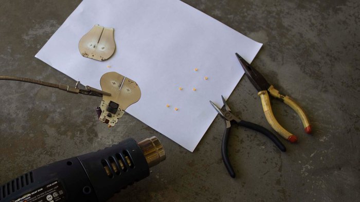
I deployed the heat gun I’ve used to remove many components from PCBs before. It is usually just for fun, or for removing hardy components like switches, transformer coils, and power connectors. This would be the first time I tried removing a silicon component with intention of reuse.


Out of eight modules, two were damaged when I tried to remove them. These LED modules were composed of two parts: a substrate to which the set of 10 LEDs were mounted, and a diffuser/cover module over them. And much to my chagrin – they weren’t bonded very tightly to each other. Here are pictures of one of the damaged modules. One LED was clearly torn off and embedded in the cover, or else I would have been tempted to power it up just to see if it works. (The LEDs are not powered in the picture, they appear bright via reflected ambient light.)

LED module with ruler

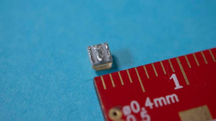
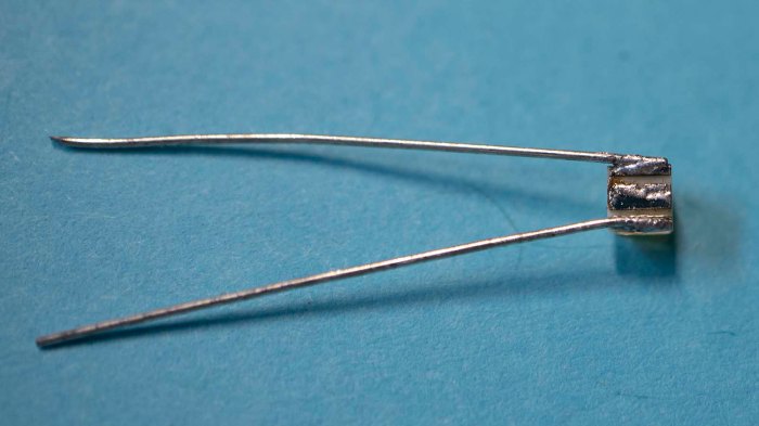
I considered trying to repair that module, by adding a blob of solder to bridge the gap where the damaged LED used to live. But it proved beyond my skill level to work at such sub-millimeter scales. Here is one of the successfully removed modules next to a ruler showing millimeters.

LED module with 3 soldered wires

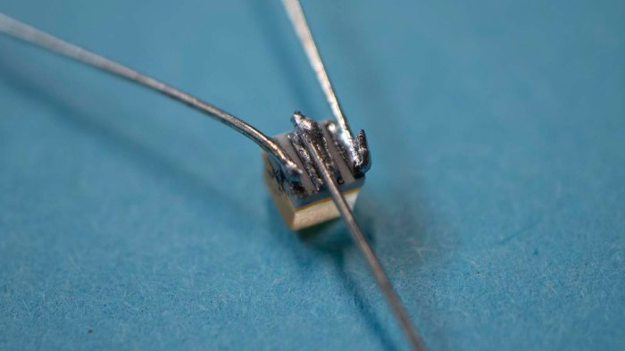
There are three solderable contacts at the bottom of each module where I expected just two. So they would be positive, negative, and… something else? To try to figure out which pad did what, I soldered a small wire (trimmed from the end of a resistor) to each pad. This turned out to be even more difficult than its small size suggested. The first wire wasn’t too bad, but when I tried to solder on a second wire I understood the challenge. This module is so small there’s very little heat dissipation between adjacent pads. As soon as I heat up one solder joint, it is hot enough to melt solder on remaining pads too. This was really designed for SMD soldering by machine, where the solder is supposed to all melt at once. Soldering one at a time by hand was hard.

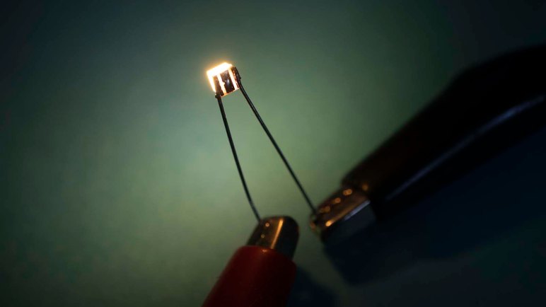
Once soldered, I connected power to two of the three pins. It appears the center solder point is not for power. My best guess is that it is for heat dissipation and apparently a wire soldered to the pad does not offer enough dissipation to tolerate abuse. As a test I cranked up the power (over 30V and over 40mA). That heated up the LED enough to melt the solder and escape, falling off the wires onto my workbench.

LED module with 2 soldered wires

Which meant another opportunity to practice patience while soldering. This time I didn’t bother soldering to the center pad, and I didn’t crank the power up as high.

LED module illuminated

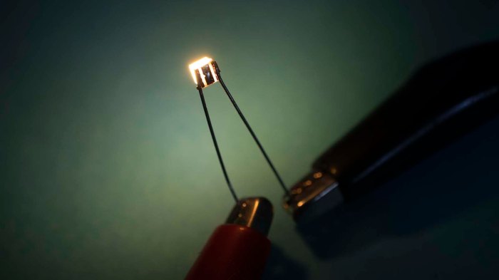
These LED modules give a dull glow at 24V, drawing less than 10 mA while doing so. They start growing brightly at roughly 27V, drawing approximately 20mA. I’ll need to provide better heat dissipation, connected to that center pad, before I push through power any higher again.

Successfully Ran Multi Hour Programs With bCNC

Once we added a crude but functioning third axis to our primordial CNC machine, we started testing it by running longer and longer G-code programs. Once we got to a test program that took roughly 25 minutes to complete, we encountered our first system failure: our computer running UGS (Universal G-code Sender) would lose its serial communication connection at unpredictable times.

As we intend to eventually run programs much longer than 25 minutes, this was unacceptable and UGS was removed from contention. We returned to the list of G-code senders in Grbl documentation and chose bCNC as our next candidate.

We are definitely giving up some nice features by moving from UGS to bCNC. We lose the ability to customize the arrangement of our control elements, and we lose the ability to preview our tool path from arbitrary directions. (We’re restricted to a few fixed projections.) But reliability is more important than eye candy, so we’re happy to give them up if it means a system that we can rely upon to run for hours.

To test bCNC, we take advantage of the fact this is an open loop system: the control board will run exactly the same whether it is attached to the salvaged industrial XY stage or not. This allowed me to run long duration tests using just the laptop and the prototype control board, away from the workshop where the machine hardware resides.

To establish our baseline: UGS is brought up to run this 25 minute test program again in the test configuration without hardware. Two attempts both failed with serial connection dropping offline at different times.

Then, using the same desktop test configuration, bCNC is brought up to run the same 25 minute test program. Five attempts ran to successful completion without losing serial connection.

Then we moved on to the challenge level: a G-code program that takes over 7 hours to execute. I would leave the laptop and prototype board running over most of a week. Every time I noticed the program had succeeded, I press “Cycle Start” again. This netted roughly ten attempts, and they were all successful. No serial connections were lost.

It looks like bCNC is the way to go. And with the new candidate software in place, attention returns to machine hardware.

Tool-less Corner Steering Motor Cover for JPL Open Source Rover

While building a JPL Open Source Rover, I would put the rover chassis in many different orientations in order to better access whichever part I was working on at the time. I’ve experienced recurring problems with the default corner steering motor cover popping off under sideways load, which happens when I have the rover on its side or on its back. The motors themselves are relatively robust but the wiring terminals at the end are fragile and difficult to repair if broken off. So I’d like to keep them protected as I work on other parts of the rover. I know I’m prone to accidental bumps that, thanks to Murphy’s Law, tend to impact the fragile and difficult to repair parts of my project.

Thus the motivation for this quick 3D printing project: an alternate design for steering motor covers. I had the following project goals:

  • Easy to print, without overhangs that would require support.
  • Tool-less installation and removal
  • Robust against sideways forces
  • Round shape to reduce chance of catching on obstacles.

In order to take advantage of nature of 3D printed parts, it was broken up into two pieces. The inner clip is printed at an orientation suited to clip onto the Actobotics aluminum rail without worrying about layer separation. The cap is printed at an orientation that makes it easy to print without supports. Separating the cap from the clip also makes it easy to create variants on the cap without worrying about compromising the Actobotics clipping capability.

With these caps installed on my corner steering motors, I was able to work in various orientations without worry of the cap falling off. I could also move the rover about and, thanks to the round surface, the cap is unlikely to catch on things and fall off. So even if a rover ultimately has plans for other caps, the round cap is still useful to have installed during construction and maintenance.

I’ve released this design on the JPL rover builder’s forum, hoping others would find it useful to build upon. The original CAD is a public document in Onshape, the read-to-print STLs have been uploaded to Thingiverse, and a video walkthrough explaining how it works has been posted to YouTube.

Unreliable Serial Communication with UGS, Try bCNC Next

We now have a three-axis machine: aged but still robust industrial motion control linear drives for our X and Y axis, and a new but not at all robust servo holding a Sharpie marker as our Z-axis. It was enough to let us feed three-axis G-code programs and watch them in action.

We started with short programs that would take less than a minute to run, then gradually increased the complexity and duration of jobs. If we wanted to turn this into a CNC mill, it will need to be reliable and dependable for long jobs. We didn’t have enough experience to have a list of potential points of failure, we just ran ever longer jobs and watched to see what goes wrong. We knew it was going to be a process of finding a problem, fixing it, finding the next thing to fail, fix that too, and repeat.

Our first problem: the G-code sender UGS running on the control console laptop. In the middle of running a job of approximately 15 minutes, UGS would drop serial connection. The machine stops moving and UI shows “OFF-LINE”. This is not just annoying, it is plainly unacceptable in a machine that might be expected to run for hours.

And there’s another possibly related problem with UGS serial communication: it was not able to connect to Grbl ESP32 if the dev board was connected at boot. We could work around this by unplugging the USB cable to ESP32 and reconnect, but this is rather inconvenient.

We could put up with the startup connection issue if that was the only problem, but randomly halting in the middle of a long job is unacceptable. So UGS is out of contention, and we return to the Grbl G-code sender list to find a replacement.

The next candidate: bCNC.

Quick Fabrication For Servo Z-Axis

Soldering up components for a test run at the workshop, I ran out of time to implement something to actually attach to the end of the Z-axis servo. While I was setting up all the components with copious amounts of tape, I asked Emily for help. She has repeatedly demonstrated skill at creatively building a solution in very short time using whatever parts were on hand. The most important episode of this skill saving our bacon was when she fabricated a steering servo bracket for SGVHAK rover.

As I was focused on routing wires and taping them in place, I didn’t watch the magic happen first hand. But I was amazed when Emily walked up less than 15 minutes later with a bracket with parts clearly made of 3D printed plastic. There was not enough time to print such a thing… “How did you do that so fast?”

As it turned out, she drew from a box of rejected & failed 3D prints that was sitting in the back of the shop. The parts were not printed for this project, but their residence in the fail pile made them candidate raw material for today’s quick fabrication. Once Emily installed the Sharpie marker holder to our servo Z-axis, our plotter can lift its pen!

Emily rigging up Sharpie holder for Grbl ESP32 Z axis servo

But as we found out very quickly, the lift is not clean. This cheap micro servo has a lot of slop which made it difficult to position it at a height that will make good contact with the paper when down and stay clear of the paper when lifting. Instead of ending a line cleanly, the pen would make a short diagonal mark as it lifted.

No matter, it was enough for us to continue testing this system. We started feeding it increasingly longer programs to see what breaks down first. Our answer: UGS, the G-code sender program running on our control console laptop, was the first to fail.

This Test Run Made Possible By Tape

Completion of soldering circuits for hardware control switches seemed like a good place to take a break and test. It’s fun to keep the momentum going, but it’s also important to stop and verify the work done so far. Off to the shop we go to set things up!

The jury-rigged nature of this prototype test is evident. While I had put a bit of time into building a nice shelf for the computer, none of the other pieces received such attention. Eventually there’ll be an enclosure for the ESP32 running Grbl. A circuit board of the dev module plus all of its associated circuitry, much like the official Grbl ESP32 board. But that board has room for Pololu stepper drivers like those on a 3D printer, and we don’t need that for our Parker motors. That will happen later. For this test, I found a piece of scrap acrylic and taped it to the top extrusion beam to serve as table for the perforated circuit board.

In fact, tape is the dominant element in this test. In addition to the ESP32 platform, tape is held the battery pack for Z-axis servo. Plus all the wires, as it’s not yet clear how we’d want to run wiring for this system. The Parker ZETA4 drivers are still sitting loosely on the bottom shelf of the table, they need to be properly mounted eventually. Once these drivers and the ESP32 are mounted, we will need to consider how to best run wiring to minimize chances of wires getting in the way of our work piece.

In the meantime, everything is held out of the way with tape. Tape tape tape.

Aside from the computer, about the only thing not held by tape was the servo I intended to use to test Z-axis, which received a small 3D printed bracket. However, I ran out of time at home before I could devise something to attach to that servo output shaft.

For that I had to call for help, and Emily answered.

Sawppy Attends MatterHackers Modern Creators Night

MatterHackers is a local supplier for 3D printing. They also carry other products catering to the same hobbyist-grade audience for small scale fabrication, such as laser cutters and CNC engravers. I’ve bought much of my supplies — including the PETG filament used to print the current iteration of Sawppy — from MatterHackers.

I’ve met some of the people of MatterHackers at Yuri’s Night, and been extended an invitation to visit their headquarters where there’s a showroom area. But I have yet to take them up on that invitations because, while MatterHackers is within driving distance, it is a nontrivial drive accounting for LA traffic. Going to that area is basically a day trip, and it kept not happening.

But when Sawppy was invited to be at their Modern Creators Night event, that was enough motivation for me to pack up and take that trip. At the event, I learned it is a scaled-up version of an occasional meetup MatterHackers used to hold at their main office, but there was no longer enough space there. Their business has grown, as has the size of the crowds. Hence – a new event at a venue with a new format.

Sawppy arrived and started roaming the exhibit area as rovers tend to do. But when it came time for the speakers to present, Sawppy was presented with a table for static exhibit. I made some signage I could tape to the table, to explain Sawppy when I’m not present to tell the story.

Sawppy on small MatterHackers display table

There were a lot of 3D prints on exhibit by other makers, and one of them decided to loan their little printed model of Curiosity to keep Sawppy company during speaker presentations. I was happily surprised when I saw this little guy, and didn’t meet its owner until later. I regret to say I’ve already forgotten her name, but her generous and appropriate loan is very much appreciated!

Sawppys little friend

Wire Up Hardware Control Switches

After wiring up for Z-axis servo control, I turned my attention to the remaining empty quadrant of the prototype board.

At the moment I have a small laptop running a G-code sender acting as the CNC control console, from which I can access all functionality of Grbl. The ESP32 port of Grbl also offers a built-in web interface, which is a great choice for compact machines that don’t want the overhead of a full computer. Both of these control options have a communication delay, so some things are better handled by hardware switches for immediate feedback.

By default Grbl ESP32 supports four physical switches, in the order of their pin assignment they are:

  1. Feed Hold: On many CNC, this completes execution of the current G-code command but holds off running the next one. Some machines can pause mid-command but this is not guaranteed. Axis motion stops, but spindle does not. This is a good way to have a machine pause, useful for example when the operator wants to visually check to make sure position and upcoming commands look reasonable.
  2. Cycle Start: Begins executing the loaded G-code program. Also used to resume execution after Feed Hold.
  3. Reset: This commands an immediate stop, of everything. Unlike Feed Hold, it will not wait for the current command to complete. It will also turn off spindle in addition to axis motion. Since it is an immediate cutoff of execution, the controller ends up in an unpredictable state. There’s no resuming after a reset. The machine has to be re-homed and all coordinate offsets recalculated.
  4. Door: Designed to be wired up to a door open detection switch so the machine can take actions to ensure operator safety. On some machines this is effectively a Feed Hold, others treat it as an emergency Reset, most machines treat it as somewhere in between. I don’t know yet how Grbl reacts.

All four are designed for normally-open switches that activate upon closing the circuit to ground. For reasons I don’t understand, these switches don’t use the ESP32 internal pull-ups and require external pull-up resistors. Normally-open switches don’t necessarily make sense for a situation. For example, reset is usually wired up with a series of normally closed switches and, if any of them should open, the machine halts. But this is easy to address in the physical circuit.

Another concern for these switches is that they tend to have long runs of wire. (Such as  the aforementioned reset switch.) Long wires have a nasty tendency to act as an antenna picking up stray signals. So a real board would require opto-isolation to avoid triggering from line noise. But again, this is a prototype board missing the full set of protective features.

After I wired up jumpers for playing with these four switches, I made a small piece of label to remind me which pin is which. Then it’s time to bring the results of this prototype soldering session to the shop and run a few tests.

Z-Axis Servo and Battery Box

I plan to take advantage of a feature in Grbl ESP32, where a RC hobby servo can take the place of a stepper motor for any supported axis. It won’t be nearly as precise, or have the same range of motion, but it’s a good option for specific situations including tests.

The first part of this task was, obviously, to find it in the code repository and know how to compile with this option active. The second is to wire up my ESP32 dev board to emit the 1-2 ms RC control signal at its 3.3V output and convert that to a 5V signal courtesy of the USB port. Then it’s time to connect a servo.

But not directly, because USB doesn’t supply very much current and would not be a good source for servo motor power. Tasks with high stress or moving quickly will draw more than what USB can supply and cause voltage level to sag. Possibly causing the ESP32 to brown out and restart which would ruin everything.

What I needed for a servo test was a separate power supply. I started digging through my collection of salvaged AC to DC power transformer bricks looking for one in an appropriate voltage range before I decided I was overthinking things. This isn’t going to be the long term solution, it’s just for a short test. I don’t need a long term power source.

RC hobby servos are originally designed to run off 4.8-6V of a four-cell pack of batteries, tracing its lineage back to the age of NiCad radio receiver packs. This is roughly the same voltage as a commodity AA battery cell, so I pulled from my stock of 4xAA battery holders (*) for this test. They even have an integrated on/off switch for convenience.

The ground wire was connected to the servo ground wire as well as ESP32 ground. Servo power wire is supplied by this 4xAA tray, and servo control signal from the 3-pin servo header of the prototype controller board. And finally, the servo gets a 3D printed bracket to clip on to the gantry structure’s 40mm extrusion beams.

The Z-axis test arrangement is now complete. But before I wrap up this session of perf board soldering, I wired up provisions for hardware control switches.


(*) Disclosure: As an Amazon Associate I earn from qualifying purchases.

Wiring For Both Options Of Z-Axis Motion

Strictly speaking, it was not critical to add a shelf for the little laptop used to control everything, but it is very nice to resolve the constant irritation of pausing what I wanted to do just to find a place to set it down. It should speed up future tinkiering of this machine, and the next step in that process is to wire up Z-axis capability.

In hindsight I should have packed the X (lower left) and Y axis (lower right) components a little closer together, but learning these lessons this is why we build prototypes. There isn’t quite enough room to duplicate the same pin layout for Z in the upper right, but then again, I don’t really need to. I’m not interfacing with an existing Parker Motion Control product, the Z-axis will be different.

As a result, the JST-XH connectors have been simplified from a 4+3 arrangement to a single 6-pin arrangement. 4 of the pins are the same: a pair of open-drain signals for step and direction. The remaining two pins are for a normally-open switch to home the Z axis stepper control.

But there’s another twist to the Z-axis: a feature of Grbl ESP32 is the ability to use a RC hobby servo for any axis. It requires changing a few #define in the source code and recompiling, something I could do on the little laptop who now has a shelf. I thought a servo-actuated Z-axis would work well as a first test of system functionality, before I go through the effort of building a more functional stepper-controlled Z axis.

But I couldn’t use the same pin for both, because an open-drain circuit is the wrong way to send a control signal to a servo. Instead, a separate transistor was rigged up so the ESP32 control signal (3.3V) can emit a 5V servo signal. The signal pin and ground are exposed via a separate 3-pin header.

The 5V source for the control signal came from the USB port connected to the little laptop. Ideally there’ll be some opto-isolation for the control signal, but this will suffice for a prototype. However, it will not be enough to power the servo motor, which will require its own power source.

A Shelf For CNC Console Computer

The first thing I wanted to address after a wobbly (but successful!) first run was placement of the control console computer. I didn’t have a good place to set the tiny laptop down. The machine may not look like it would take up the entire table, but once machine’s range of motion is accounted for, there’s not a whole lot of space left. During the test run, the laptop was literally on the ground next to the table. It would be useful to have a dedicated computer shelf.

The shelf was designed in two parts. The right side could be bolted to the end of an extrusion beam, but the left side didn’t have that luxury. I thought I would design it to clip on to the extrusion beam, but the first draft hooks were far too aggressive. I had to trim them back with a saw before I could fit the piece around the beam.

HAKCNC computer shelf overly agressive claws

Both hooks installed and ready to host the computer. The right hand hook was printed with the final filament from one spool and start of another spool of PLA. Even though I ordered from the same vendor (Monoprice) they have apparently changed vendors or specification and the new spool filament is visibly different.

HAKCNC computer shelf in place

At first glance this design may appear to be heavily cantilevered, with most of the weight on the front of the hook placing great stress on the mounting points. This is only true when the laptop lid is closed. When the lid is open, where this shelf mounts on the beams is actually very close to the center of gravity of the laptop.

It still needs to be able to accept some weight, though, since there’ll be physical forces as I type on the keyboard and use the trackpad. But PLA is plenty strong for this application, with very little flex even when I rest my wrists on the computer.

This shelf is probably not permanent, but it is nice to have a convenient shelf to hold the laptop while I figure out how to work the rest of this machine.

3D Printed Spacer For Rover RoboClaw

A 3D printer is not a fast worker, but as slow as they are, they are still faster than waiting for shipping. This means owning a 3D printer can sometimes be a convenience feature, unblocking project progress while real objects are in transit or perhaps substituting them entirely.

While following the current iteration of JPL Open Source Rover instructions, I was tripped up by an error in the parts list reference. As a practical matter, it meant I didn’t have the aluminum spacers on hand to mount RoboClaw motor controllers to the rover mainboard. Once I understood what was going on and filed the issue on Github, I ordered correct parts from McMaster-Carr and they will arrive in a few days.

But what do I do in the meantime? If I’m not able or willing to wait for the correct spacers, I can design and print my own. It is a very simple shape and a small part that will be quick to print. I didn’t model the threads but it would have been too fine to print anyway – the screws will just self-tap into 3D-printed plastic.

Here are 3 printed and 1 metal spacers on a test run on the rover mainboard, before I installed a RoboClaw to verify all parts worked as planned.

RoboClaw spacer 3P1M

While these plastic parts are weaker than the proper aluminum bits, in this particular application I don’t expect the material strength differences to matter. What is far more useful is the fact they are here right now and I did not have to wait for an UPS truck.