Manual Control Square Peg in a ROS Round Hole

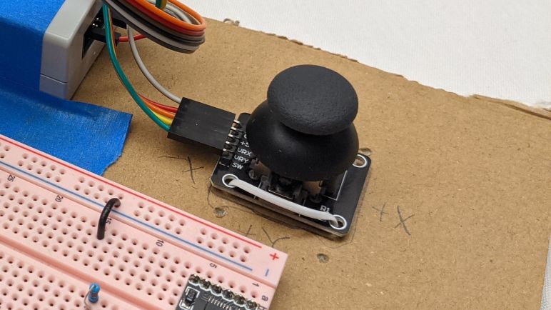
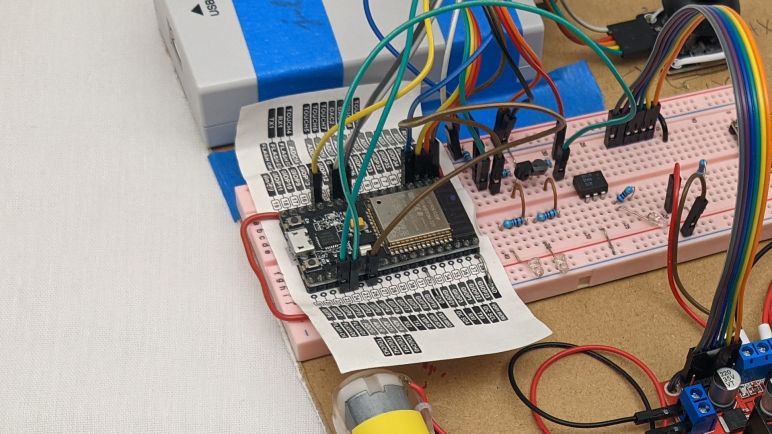
I have converted my test code reading a joystick via ESP32 ADC peripheral to generate ROS-like data messages as output. There were some hiccups along the way but it’s good enough to proceed. The next step in the pipeline is to interpret those joystick commands in a little Sawppy rover context and generate ROS-like robot chassis velocity command (cmd_vel) as output. And as I start tackling the math I realized I’m going to face a recurring theme. I have some specific concepts around manual control of a little Sawppy rover, but those concepts aren’t a good fit for ROS conventions like REP103.

The first concept is velocity. ROS command for linear velocity is specified in meters per second. There’s no good way to say “go as fast as you can go”. Specifying meters per second will never be accurate on an open-loop DC motor system like micro Sawppy for multiple reasons. The first and most obvious one is battery power: full speed will be faster on a fully charged battery. The next problem is robot geometry. When traveling in an arc, Sawppy’s top speed will be constrained by the top speed of the outer-most wheel. As the arc tightens, that outer-most wheel running as fast as it could would still constrain the rover to a lower top speed. So Sawppy’s top speed will vary based on other conditions in the system.

The second concept is rotation. ROS command for angular velocity is specified in radians per second. There’s no good way to say “pivot about the rover’s inner wheel” because the center of the turn is dictated by the combination of linear and angular velocity. Thus the center of the turn is a result of (instead of a part of) the command. In my experience I’ve found that people have a hard time working with Sawppy turning radius when the center of turn is inside the rover’s footprint. People have an easy time with turns that resemble the cars we see on the roads everyday. People also had no problem with Sawppy pirouetting around the center axis. But in between those realms, people get confused pretty quickly. When I created the wired controller for Sawppy, I divided up the control space into two regimes: One mode where Sawppy pivots in place, and another mode where Sawppy’s turning radius is constrained to be no tighter than pivoting on one of the middle wheels. Deliberately constraining Sawppy’s maneuverability to be a subset of its capabilities was a worthwhile tradeoff to reduce user confusion .

But the whole reason of ROS is autonomy, and autonomous robots have no problem dealing with all degrees of freedom in robot movement, so there’s no reason to block off a subset of capability. However, that also meant if I’m structuring the manual joystick control system to follow ROS conventions, I have no easy way to block off that subset for human friendliness. It is certainly possible to do so with lots of trigonometry, but it always makes my head hurt. ROS works in radians and I have yet to develop a good intuitive sense for thinking about angles in radians. All of my mental geometry have been working in degrees.

These are but two of the problems on the road ahead for Sawppy, in its first draft as a manual remote-controlled vehicle. I hold out hope that this up front pain will make Sawppy software work easier in the future as I adapt ROS nodes to give Sawppy autonomy. But it does mean making today’s manual control Sawppy a square peg trying to fit in a round hole, with lots of imprecision that will fall to “best effort” basis instead of rigidly complying with expectations of ROS. But I’ll stay with it to the best of my abilities, which means revisiting rover geometry math in this new context.

Joystick Range Check Works Around ESP32 ADC Mystery

One of the things I knew I wanted to do for my Micro Sawppy rover’s ESP32 brain was an option for wired analog joystick input. This proved useful for Sawppy V1 and I wanted it for Micro Sawppy as well. Not just as a backup control method, but as the first test in my hypothesis that I will benefit from following ROS precedents for generic messages. In addition to the evergreen ambition to give Sawppy autonomy, I want to support the following manual input control mechanisms:

  • Wired analog joystick for noisy wireless signal environments.
  • Web-based control similar to what I created for SGVHAK rover and adapted to Sawppy.
  • Bluetooth based control to connect with devices like the BBC micro:bit.
  • ROS2 joystick control message via micro-ROS.

If I have a generic message type resembling ROS joystick message, each of these input methods can theoretically be isolated in their own FreeRTOS tasks. They all post the same message type to the same message queue, so the rest of Micro Sawppy doesn’t have to care about where their input came from. Swapping input was something very difficult to do on SGVHAK rover software and I want to do improve this time around.

So as a starting point I wanted to take my quick hack of ADC joystick support in my FreeRTOS play project and rewrite it to be something suitably robust for Micro Sawppy. Since it was a quick hack, there were a few weird things that happened but I chose not to worry about it at the time. Thinking I’ll sit down and figure it out later. It is later and… I failed to figure it out. But I did devise a workaround so I can continue with the project. I’ll come back and update this paragraph if I figure it out later.

The issue center around ESP32’s ADC (analog-to-digital converter) peripheral. I had been familiar with ADC peripheral on a Arduino’s ATmega328, which can read values in a range from 0V to +5V via analogRead(). The ADC on a PIC16F18345 works in a similar manner. The ESP32 is a 3.3V chip so I had expected its ADC to read the range from 0V to +3.3V but I was wrong. By default it only reads from 0V to 0.8V. We can configure a signal attenuator to increase range of ADC sensitivity, but even at maximum attenuation it only claims to read from 0V to 2.6V.

This presents an issue with analog joystick inputs, which are electrically potentiometers that feed a voltage value somewhere between its input max voltage and ground. Wiring such a device up to the ESP32’s 3.3V supply means we’ll lose the ability to read the high end of the joystick corresponding to the range between ADC maximum of 2.6V and 3.3V. It also means the joystick’s center position will return about 1.65V which is higher than midway between 0V and 2.6V. So I had expected ADC readings to be higher than what I would expect.

The reality was just the opposite, they were lower instead. I configured the ADC for 9-bits resolution, so the values are anywhere from 0 to 511. Midway would be 256, but joystick center actually correlated to ~220. And even though I expect to hit maximum value partway through the high range of joystick motion, I never got there. Maximum value never exceeded ~460. I used a voltmeter to measure the input and confirmed +3.3V, but the reading wasn’t close to the actual maximum value of 511. Several rounds of fiddling with configuration flags did not change this result.

So as a workaround, my new joystick code does a range check upon powerup. It assumes the joystick is centered at powerup (hopefully reasonable assumption when they are spring loaded) and waits for me to move each axis through its minimum and maximum values and press the button. Before that first button press, my code tracks the highest and lowest values seen, which are used to normalize joystick message output to the range from -1 to +1 that is used in ROS joystick message. I’m using some very inexpensive joysticks whose potentiometers drift significantly, so maybe a range check is a good idea anyway. Either way it’s good enough for me to move on.

Goals and Challenges for Sawppy ESP32 Software

With a cardboard rover test platform ready to go, I’ve run out of excuses to put off the software portion of micro Sawppy rover work. If my little rover is going to come alive, the software work must be done. This task shouldn’t be as intimidating as it feels, because this is my second round through writing rover brain code. I have learned some lessons from writing SGVHAK rover code running on a Raspberry Pi (code which I then adapted to Sawppy) and those lessons should help me this time on the ESP32.

One goal for my new ESP32 project is to be more ROS-friendly. I’m not ready to dive straight into micro-ROS right now. But when I (or someone else) tackles the challenge, the project shouldn’t be tripped up by something that needlessly complicates the task. I wrote SGVHAK rover code before I knew much about ROS, and in hindsight I made some decisions that made a ROS port annoying for no good reason. For example, the ROS convention for robot forward is along the +X axis. Ignorant of this when I wrote SGVHAK rover software, I chose forward to be +Y axis. The ROS convention for angular measurements are radians for units, and the right-hand rule for positive rotation. Meaning a positive rover steering rotation is counter-clockwise. For SGVHAK rover, I worked with angles in degrees and positive rotation was clockwise. There was no reason to go against these ROS conventions, it was done purely out of ignorance. If I were to adapt my SGVHAK rover code to ROS, a whole bunch of conversions need to occur risking additional surface area for bugs. I completely understand why Rhys Mainwaring wrote a rover ROS software stack from scratch instead, I would have done the same!

So for my upcoming ESP32 Sawppy rover brain project, I’ll keep ROS conventions in mind. Specifically REP103 for units and coordinate conventions. Another ROS-inspired similarity will be messages, which is a new luxury gained by the change in platform. For SGVHAK rover I avoided the complications of introducing multiprocessing concepts to Python code running on a Raspberry Pi. But now I’m targeting the customized FreeRTOS Espressif created to run an ESP32, I gain a lot of multiprocessing tools as a natural and fundamental part of the platform. I will be organizing my code components into FreeRTOS tasks, which has similarities to how ROS organizes code components into nodes. So when my tasks communicate with each other, I’ll look to see if there is a ROS equivalent. I won’t be able to make my FreeRTOS messages compatible with ROS message formats, though. Because I won’t have some of the luxuries like dynamically sized arrays. But the data organization should at least look similar.

I foresee the following items, and I’ll probably find more as I go:

  • I will rewrite my ESP32 ADC joystick code to communicate with a new data message. It should resemble sensor_msgs/Joy from ROS, normalized to the same value ranges.
  • When I write the task which translates raw input into desired rover chassis command, that result will be communicated with something that resembles geometry_msgs/Twist used for ROS topic cmd_vel (Commanded Velocity).
  • When that cmd_vel command is broken down to commands for individual motors and actuators, those individual commands should resemble joint commands of ros_control. I have not yet worked with ros_control myself so this one is the fuzziest with the most unknowns. But I look forward to learning!

And as expected of a learning project, I ran into problems immediately with the first item on the list. I eventually decided to devise a workaround for ESP32 ADC behavior I don’t understand yet.

Micro Sawppy Rover Cardboard Box Testbed

Proving that I could control DRV8833 DC motor driver IC using an ESP32 was the final piece of the foundation I knew I needed before I seriously start building a micro Sawppy rover brain on an ESP32. During my development of this software, I will need a physical chassis to test code on. While I could go straight to my Micro Sawppy Beta 3 (MSB3) chassis, doing so has the risk of breaking physical robot hardware. Anything from a servo moving beyond intended limits, to embarrassing mistakes like driving the rover off the table.

A safer option is to have a representative testbed with fewer risks than a physical robot. For my original Sawppy rover, I removed all ten LX-16A serial bus servos and laid them out on a table. I found that a line of servos wasn’t very good at conveying system behavior, since I had to do some mental spatial transforms in my head to interpret those servo movements. Some bugs slipped through this process because I made mistakes in my mental visualization. From that experience I thought it would be better to have a testbed that better represented the physical layout of the rover chassis, and this is an opportunity to put that idea to the test.

In line with my recent discovery of cardboard for mockup purposes, I pulled a cardboard box from my paper recycle bin. I turned the box inside-out to give me some clean note-scribbling surfaces, plus I’m not advertising that product on this site anyway. Holes were cut in the cardboard so I could use twist ties to fasten six TT gearmotors in the same relative location as they would be on a rover. I also cut four rectangular holes for the steering micro servos. Since I cut those holes by hand, the imperfections of the manual cut gave the servos enough friction to sit in place without any fasteners.

Wires for all of these components went into the box, and small holes were cut so they could poke through to this top surface. This routing keeps all excess lengths of wire out of my way making for a neater work area. The ESP32-based control board, whatever it ends up being, should fit in the center area I kept clear for it. Excess wire isn’t the only thing I kept in the box, it was also a convenient place to store all the related auxiliary pieces related to the project. Each micro servo has a plastic bag with spare control horns as well as their mounting screws not needed for the testbed. And each gearmotor came with a wheel that’s not strictly necessary for the testbed. There’s a chance I’ll want these wheels later, to better visualize relative rotation velocity of the wheels. If that should occur I know where to find the wheels: they’re in the box!

But first I need to get started with Sawppy ESP32 software.

Test Driving DRV8833 With ESP32 MCPWM

It was time well spent to study my batch of commodity breakout boards for the DRV8833 DC motor driver IC. It reinforced that I should not take random instructions downloaded online at face value, even though in this case the errors wouldn’t have been relevant to my planned usage. Armed with confidence I understand how to use the board I have on hand, I proceed to the next step: verify I could write code to control one with an ESP32 and its MCPWM peripheral.

My self-education FreeRTOS project was created with this future in mind when I started by controlling a L298 DC motor driver IC. The first exercise used the control scheme utilizing three pins per motor (two digital for state, one PWM pin for magnitude) which is compatible with the TB6612 but not DRV8833. The beauty of FreeRTOS was that I was able to isolate code specific to this control scheme in its own FreeRTOS task. In theory, all I would need to do is to write another task with DRV8833’s control scheme (a pair of PWM pins per motor) and swap out the motor driver control task. The remainder of my test program, from the joystick ADC to the heartbeat status LED, would remain untouched and blissfully unaware I’ve switched my motor control task.

I’m happy to report theory matched practice this time! The problem I encountered was unrelated to FreeRTOS. It was really easy to get one motor up and running but I was tripped up by my misinterpretation of Espressif documentation when trying to run two motors simultaneously at different speeds. Each MCPWM unit on a ESP32 can control three motors, and each MCPWM unit had three timers. The quote from Espressif documentation that I misunderstood was:

Each A/B pair may be clocked by any one of the three timers Timer 0, 1 and 2. The same timer may be used to clock more than one pair of PWM outputs.

I tried to run two pairs of PWM outputs (one pair per motor) with the same timer, which is explicitly allowed by the documentation and generated no compiler or runtime errors. However, the fact that it is possible and allowed doesn’t mean it actually does what I want. By using the same timer, I had also locked those motors to the same speed. Different speeds require separate timers. Which is why MCPWM offers up to three timers so we can run each motor at a different speed. Once I realized my mistake and understood what was going on, it was an easy fix to get both motors up and running each with their own timer. With both motors running on my existing cardboard testbed, I thought it was time to upgrade to a fancier (but still cardboard) testbed.


This coding practice project is publicly available on GitHub.

Notes on Commodity DRV8833 Breakout Board

Having read through the datasheet for DRV8833 DC motor driver IC, I was optimistic that they would be a good choice to control DC motors on the TT gearmotors I have installed on Micro Sawppy Beta 3 (MSB3) rover. DRV8833 operating voltage range of up to 10V is a much better fit for these 3-6V motors. Compared to the classic L298N motor controller with its 4 to 45V range. The lower voltage handling requirements, as well as being a much newer design using modern power management techniques, means a DRV8833 breakout board is far more compact than a L298N breakout board. Something clearly visible in this side-by-side picture. Physical volume is an important consideration when fitting electronics inside a little rover.

Side by side size comparison of L298N and DRV8833 motor control IC breakout boards.

For my first round of experiments, I bought a batch of 5 DRV8833 breakout boards from the lowest bidder of the day on Amazon (*) I’m sure a different day will have a different lowest vendor when we issue a query for DRV8833(*), because these breakout boards seem to be commodities offered by many different vendors. We also see this particular design from many vendors on AliExpress. I noticed two or three very popular designs for a DRV8833 breakout board. I have no idea where this particular design came from. If the same factory is supplying all of these vendors, or if the design has been cloned by multiple manufacturers. Whatever the history, I see enough quantity to give me confidence these boards won’t disappear overnight. We’ll see if I’m right!

Incorrect instructions shown on some DRV8833 product listings.

In this particular product listing, one of the pictures serve as a rudimentary reference manual for the board. I was suspicious of these instructions so I probed this board to determine the circuit for myself as I did for the L298N board. I’m glad I did! The instructions had swapped the “FAULT” and “SLEEP” pins for reasons unknown. Fortunately, those pins are optional so most users (including my intended use) won’t be affected.

There are only a few supporting components on this board. From the DRV8833 datasheet I expected three capacitors and they are clearly visible. I also see two resistors and a LED. The LED was not on the datasheet, it was a bonus feature to indicate power supply is present, along with its 4.7kOhm current-limiting resistor. The final resistor is a 47kOhm pull-up resistor for the SLEEP pin, by default pulling it high to enable the board and giving us the option to leave the breakout board’s (SL)EEP pin unconnected.

Back side view of a DRV8833 breakout board, showing the J1 trace that can be cut to disconnect pull-up resistor and allow control over sleep functionality.

For applications that want to assert control over sleep/enable themselves, there is a provision on the back side of this breakout board. Cutting the trace on J1 will disconnect SLEEP from the pull-up resistor, opening up the pin to external control. If we should change our minds afterwards, we can solder across J1 pads to reconnect the pull-up resistor.

No such provisions exist for current chopping control. DRV8833 offers the option to limit maximum current by putting current-sensing resistors on the AISEN and BISEN pins, but this particular breakout board design connected those pins directly to ground without any provisions to add current-sensing resistors back in. Applications that want current chopping will have to go elsewhere.

Remainder of the board was fairly straightforward, once we figure out the pin rename mapping. This board labelled its pins IN1-4 and OUT1-4 following precedent of L298N, instead of the names in the DRV8833 datasheet of pins 1 and 2 for channels A and B. For those that prefer this information in schematic form, here’s what I drew up after my probing session for this board to guide my first experiment putting one to use:

Schematic diagram for a popular type of DRV8833 breakout board.

(*) Disclosure: As an Amazon Associate I earn from qualifying purchases.

Sawppy Rover Dances Like Real Rovers

Whenever I build something physical from my imagination, the reality always served a few surprises I failed to anticipate in my mind. Two recurring themes are seeing real joints flexing beyond their primary rotation axis, and realizing physical objects aren’t as perfectly rigid as they are in CAD. Nothing exemplifies this more than the rocker-bogie suspension of my Sawppy rovers. Their movement are well-defined when I articulate them in CAD, but once printed and assembled, I saw movement that weren’t in my CAD model. When rolling over obstacles, Sawppy would wobble and bounce in response to mechanical shocks that weren’t absorbed by its curved wheel spokes. A few other Sawppy rovers builders have asked me to check if this was supposed to happen on their rovers. I answered that it was not an intentional design feature, but they have done nothing wrong as I see it on my rover as well. I joked that our rovers are just dancing.

Part of this comes from Sawppy’s low-cost construction. The aluminum extrusion beams are not as rigid as the carbon composite tubes of real Mars rovers, and the 3D-printed connectors for those beams are not as rigid as CNC-machined metal components. The commodity 608 bearings I used for Sawppy’s joints give me smooth movement and load bearing capability, but they also add some mechanical slop to the system.

But part of this came from the suspension geometry itself, which is unlike suspension systems of cars we drive here on planet earth. Due to far higher speeds involved, our car suspensions are robust and bolted to car chassis at multiple points for added rigidity. In contrast, Mars rovers experience road impacts at a far slower rate, reducing the need for a heavily braced system. Such bracing are undesirably heavy on their strict weight management regimen. So rover suspension components are rather spindly and are attached at only one (or in rare cases, two) points. With so few attachment points, and a multi-segmented construction that puts large subassemblies at the end of several joints, any component movement and flex is compounded.

I had been curious how this tradeoff manifested on real Mars-bound rovers. They have sturdier components, but Sawppy copied their geometry and share the associated challenges. I kept my eyes open on footage of Perseverance rover while it was being tested to see if I see any wobble or bounce, but those tests are slow-moving affairs that imposed no major mechanical shocks to propagate through the system. Since I don’t expect anyone to swing a sledgehammer at the rover, I had resigned to never knowing.

But then I was happily surprised when I watched video footage of Perseverance landing sequence, specifically the part where the descent stage unspooled its tethers to lower the rover. (Thanks to Emily Velasco for turning it into an animated GIF I can embed here.)

Perseverance rover descends during skycrane maneuver

During this sequence, Perseverance suspension was released from its compact travel configuration and unfolded to its driving configuration in preparation for landing. This drop-and-lock action imposed mechanical shock on rover suspension elements, and we can see everything wobbling and bouncing just as I see frequently on my own little rover. It was both enlightening and entertaining to know that real Martian rovers can dance, too! They just choose not to, most of the time.

UPDATE: NASA JPL has released sounds recorded by Perseverance on-board microphone as it started driving across the Martian landscape. In that sound clip, we can hear rover suspension components flex and squeak in response to driving over surface features. Not too different from what I hear from my own Sawppy rover.


[Title image by NASA/JPL-Caltech]

Window Shopping DRV8833 DC Motor Control IC

It was a pure accident that I stumbled across the DRV8833 DC motor control IC. After a quick comparison against my original candidate TB6612 I think some DRV8833 modules might actually the better choice for my micro Sawppy rover project. Its required control signals are an ideal fit for the MCPWM peripheral on the ESP32 I planned as my rover brain. Though note not all models of the ESP32 line has MCPWM peripherals, for example it appears to be absent from the ESP32-S2.

The DRV8833 is less capable than the TB6612 in some ways. For example, the maximum voltage is listed as 10.8V which is lower than the 15V listed for TB6612, and far short of the 45V listed for a L298. But TT gearmotors are typically listed with a maximum voltage of 6V, so I should be fine. I was surprised that the amperage rating isn’t much lower, with 1.5A typical and 2A peak that should suffice for TT gearmotors. And if I need additional current carrying capacity, the DRV8833 is explicitly stated to be capable of both output stages working in parallel to double the maximum current. The L298 datasheet also explicitly listed parallel operation as an option, but the TB6612 did not.

Like the L298, the DRV8833 has provisions for current-sensing resistors between AISEN and BISEN pins to ground. But unlike the L298, the DRV8833 will actually read their voltage to limit maximum current output. The current-sensing resistors are a whole world into themselves. They work best when placed close to the IC because that minimizes variation introduced by PCB traces. But if they are close, they will be in close proximity to heat generated by the IC, which will change their resistance. Quite a few variables need to be juggled for it to work right, so I’ll probably choose to opt out of current limiting and connect those pins to ground. Fortunately the chip’s own overcurrent protection circuit works independently and will activate with or without external current-sensing resistors.

All four control pins, two for each stage, have internal pull-down resistors. Thus this chip is always in a defined state and we don’t have to worry about any particular startup sequence. Whether power arrives first or control signals arrive first, the chip will work in a known way. There are two more input pins, one to control sleep and another to signify fault. The fault signal is open-drain which would make it compatible with a lot of different circuits, but I might not have ESP32 input pins to spare for detecting fault conditions. I won’t worry about low-power sleep (at least not yet) for micro Sawppy, and in that case the recommended procedure is to pull it up with a 25-75kOhm resistor.

In addition to that optional resistor, there are three required capacitors, but no external diodes are required. Looks like the diodes to handle back-EMF from inductive loads are built in which is great news. It makes for a pretty short list of external support components, but I still don’t plan to use the chip directly. The first reason is that I have many options for breakout boards. From high quality Adafruit #3297 to the lowest bidder of the day on Amazon.(*) For low quantities it’s worth a few extra bucks to pay for an already-assembled breakout board.

The second reason is that I can’t meet proper installation requirements for the more capable DRV8833 variants. As is typical, the DRV8833 is available in several chip package formats. I was surprised to see that one of them had a much lower rating for typical amperage, a third of the others. However, peak rating stayed the same, so I suspected it’s not a limitation of the chip itself. Further reading (section 10.3.1) confirmed that maximum current of a DRV8833 is a direct function of heat dissipation and the lower-rated chip package lacked a heat conduction pad present in the others. (TI calls it PowerPAD.) Thus soldering a DRV8833 correctly requires reflow soldering. I would have to pay someone else to handle it, or buy my own reflow setup, but that’s a concern for the future. Right now I can start with some cheap breakout boards.


(*) Disclosure: As an Amazon Associate I earn from qualifying purchases.

TB6612 Vs. DRV8833 DC Motor Driver ICs for ESP32 Micro Sawppy

While researching TB6612 DC motor driver IC breakout boards on Amazon, my results list actually had more breakout boards built around the DRV8833 (and claiming TB6612 compatibility) than actual TB6612 boards. So I tried performing an Amazon query for DRV8833(*) and saw I had far more options in that category. This may change in the future as worldwide silicon supply & demand varies, but that’s the situation as I type this. I didn’t explicitly set out to find yet another candidate to replace my L298 motor driver, but since I stumbled across it, I decided to spend a bit of time to take a closer look at the DRV8833 by Texas Instruments.

First things first: the claim of TB6612 control logic compatibility is wrong. Well, technically they are compatible for applications that are only interested in powering their motors only in full forward or full reverse, but that is not realistic. Such applications would not bother with a motor control IC and would directly use some MOSFETs or even relays instead. For real motor control applications, I’ve seen two different methods to interface with the classic L298 motor control IC. TB6612 is logic compatible with one method, DRV8833 is compatible with the other method, and they are not compatible with each other.

TB6612 requires three pins: two digital pins to control behavior (forward, backward, brake, or coast) and a PWM pin to control magnitude of that behavior. DRV8833 only accepts two pins to control behavior and modulation is done by rapidly pulsing one of those pins to switch between states. Partial throttle forward, for example, is done by rapidly switching between forward and coast states. DRV8833 does not have a dedicated PWM pin like the TB6612, and the closest counterpart to a L298’s ENABLE pin is the nSLEEP pin on a DRV8833 but that pin is unsuitable for modulating velocity. The first problem is that there’s only a single nSLEEP pin for both motors, and secondly waking up from sleep requires ~1ms making smooth motion difficult if not impossible.

In general, using two pins instead of three is an advantage when we are constrained by the number of pins available, and the ESP32 certainly has that problem. However, the tradeoff is that DRV8833 requires two pins capable of generating PWM signals per motor, whereas TB6612 only requires one. This would be a concern for microcontrollers with limited PWM peripherals, but the ESP32 literally has more PWM peripheral outputs than it has usable pins.

Looking specifically at my micro Sawppy rover application, the picture of pin allocation is not quite that straightforward as (2 pins * 6 wheels = 12 pins) versus (3 pins * 6 wheels = 18 pins). In typical operation, all the wheels on one side of the rover will be traveling in the same direction, so it is possible to share the direction control pins across three wheels on the same side of the rover, cutting it down to 10 pins instead of 18. Plus if I make the rover front-back symmetric I have an additional option to share the PWM control signal across front and rear wheels, which cuts pin count down to 8. But while DRV8833 can’t share pins across wheels on the same side, it can also benefit from front-back symmetry cutting its requirements down to 8 pins as well. A tie!

Clearly there are many tradeoffs I can make with motor driver arrangement and control, depending on how many PWM peripherals are on a particular microcontroller and how many pins it has to spare. For my first iteration I like the idea of having independent control over each wheel, even though right now I’m not sure how it would be useful. Once I get that working (or learn why I can’t) I’ll look into trading off independent control for reduced pin count. So the current plan of record is to use two PWM pins for each of six wheels, driving DRV8833 DC motor control ICs.


(*) Disclosure: As an Amazon Associate I earn from qualifying purchases.

Window Shopping TB6612 DC Motor Driver IC

The cardboard backing for my latest experiment was never going to be the final arrangement, and neither are the L298 motor driver mounted using twist ties. I started experimenting with them because they were the classic, a known quantity, and widely available. But I would have expected technology to move on, and I found confirmation in this Hackaday article talking about the TB6612 motor driver IC as a replacement for those venerable L298.

I pulled up the data sheet published by manufacturer Toshiba because I wanted to learn where its specifications differed from the L298. As the article stated, this chip is not a direct drop-in replacement. In some respects this is good, for example the diodes to absorb back-EMF from inductive loads. The L298 required external support diodes, but the TB6612 has them built in, reducing parts count in our projects. In other respects the differences were limiting, such as a voltage range that only went up to 13.5V maximum which is far lower than the L298’s 45V. But since I’m looking to drive TT gearmotors which have a recommended voltage range of 3-6V, this limitation is not a problem here. And the smaller size of TB6612 would be quite welcome in a micro rover.

Examining the control signals, I see TB6612 allows us to specify motor direction using IN1 and IN2 pins. To control velocity, we send PWM signal to a pin explicitly named PWM. For applications that control a L298 using its IN1 and IN2 pins to control direction and control velocity by PWM controlling the enable (EN) pin, the TB6612 would be a direct logical replacement. However, my L298 breakout board tied EN to high by default implying speed control by PWM pulsing IN1 and IN2. I guess this is also valid for L298 but such a control scheme would not be compatible with TB6612.

Looking around, I can see the TB6612 used in a few other maker-friendly products including Adafruit product #1438 which is an Arduino motor shield built around this motor control chip. SparkFun #14451 offers it in a more compact breakout board instead of the Arduino shield form factor, Adafruit #2448 is another similar option. I haven’t built up my own equipment and skill to work with surface mount components directly, so I will need such breakout boards or pay someone else to assemble a board with it.

Examining my options on Amazon (*) I was surprised at how slim my selections were. Perhaps this is a temporary thing due to the current worldwide semiconductor shortage? Whatever the reason, the majority of my search results today were actually breakout boards for a different chip, the DRV8833, while claiming TB6612 compatibility. Since I’m in the research stage, I might as well take a look at that chip, too.


(*) Disclosure: As an Amazon Associate I earn from qualifying purchases.

Jumper Wire Headaches? Try Cardboard!

My quick ESP32 motor control project was primarily to practice software development for FreeRTOS basics, but to make it actually do something interesting I had to assemble associated hardware components. The ESP32 development kit was mounted on a breadboard, to which I’ve connected a lot of jumper wires. Several went to a Segger J-Link so I had the option of JTAG debugging. A few other pins went to potentiometers of a joystick so I could read its position, and finally a set of jumper wires to connect ESP32 output signals to a L298N motor control module. The L298N itself was connected to DC motors of a pair of TT gearboxes and a battery connector for direct power.

This arrangement resulted in an annoying number of jumper wires connecting these six separate physical components. I started doing this work on my workbench and the first two or three components were fine. But once I got up to six, things to start going wrong. While working on one part, I would inadvertently bump another part which tugs on their jumper wires, occasionally pulling them out of the breadboard. At least those pulled completely free were clearly visible, the annoying cases are wires only pulled partially free causing intermittent connections. Those were a huge pain to debug and of course I would waste time thinking it was a bug in my code when it wasn’t.

I briefly entertained the idea of designing something in CAD and 3D-print it to keep all of these components together as one assembly, but I rejected that as sheer overkill. Far too complex for what’s merely a practice project. All I needed was a physical substrate to temporarily mount these things, there must be something faster and easier than 3D printing. The answer: cardboard!

I pulled a box out of my cardboard recycle bin and cut out a sufficiently large flat panel using my Canary cutter. The joystick, L298N, and TT gearboxes had mounting holes so a few quick stabs to the cardboard gave me holes to fasten them with twist ties. (I had originally thought to use zip ties, but twist ties are more easily reused.) The J-Link and breadboard did not have convenient mounting holes, but the breadboard came backed with double-sided adhesive so I exposed a portion for sticking to the cardboard. And finally, the J-Link was held down with painter’s masking tape.

All this took less than ten minutes, far faster than designing and 3D printing something. After securing all components of this project into a single cardboard-backed physical unit, I no longer had intermittent connection problems with jumper wires accidentally pulled loose. Mounting them on a sheet of cardboard was time well spent, and its easily modified nature makes it easy for me to replace the L298 motor driver IC used in this prototype.