Once the Maker Select reached “good enough” status it was back to work printing PLA parts for Sawppy in parallel with my Maker Ultimate. This allowed me to iterate through designs much more quickly and was instrumental in getting Sawppy built in time for its first public appearance at JPL’s IT Expo.
A few problems surfaced at this event, but the one that prompted a complete reprint of Sawppy was PLA deformation under Southern California summer heat. This is where the current 3D printer story line rejoins the rover construction story line. With this experience of plastic deformation, I now have motivation to try using a different material. There are a few options, and PETG presented the best tradeoff between temperature tolerance, ease of printing, and cost.
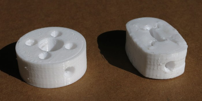
The first object to be reprinted in PETG were the steering servo couplers. This proved to be a weak point that needed to be addressed. The design was printed at 0.1mm layer height so the sideways hole for the M3 thread heat-set insert would have clear definition. (This turned out to be unnecessary – later couplers were printed at 0.3mm layer height and functioned adequately.)
I knew PETG had different requirement for printing, starting with print nozzle temperature. I started with my PLA print profile and dialed up the heat. In order to test layer bond in the print, and also to get a feel of PETG failure mode, I put the result in a vise and cranked the handle. I was happy to see PETG deformed rather than shattered as PLA would. Examination of the deformed object showed layer bonding is good. This is a good start for printing PETG.
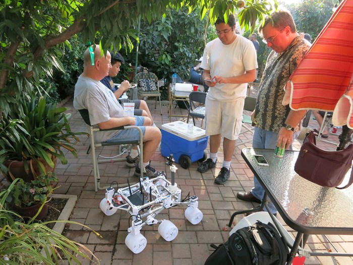
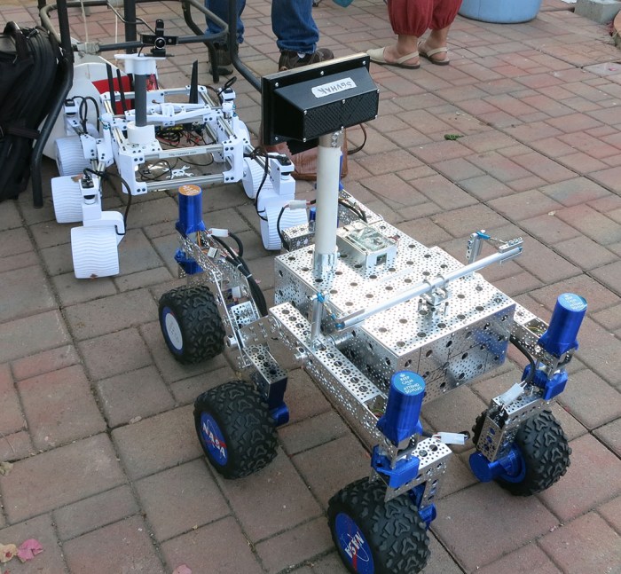
The annual summer BBQ for San Gabriel Valley Linux User’s Group (SGVLUG + offshoot subgroups like SGVHAK) was this past weekend, so obviously a few projects from the group made a showing too. This included our SGVHAK rover and my own follow-up Sawppy the Rover.
Sawppy joined the socializing first, hanging out next to some of the seats attracting attention from members who haven’t seen the motorized rover model before. (And some who have but just wanted another look.)
Later in the evening, SGVHAK rover joined on the party. The rovers would occasionally run around sometimes at the same time and sometimes into each other. They sort of got into the way of people at times, getting underfoot like a big cat might. Fortunately nobody tripped and fell over a rover.
This was Sawppy’s first public outing since conversion to PETG, a conversion motivated by earlier PLA parts that deformed under heat. This weekend turned out to be a great test since the entire region is in the middle of a record-breaking heat wave. And this time, Sawppy did not melt under the scorching sun.
Sawppy also got a few different pilots, as anyone who expressed interest was offered a chance to take the helm. Partially to share the toy, but also to get some time seeing Sawppy driven by people who don’t drive the same way I do. The intent was to probe for unknown areas of weakness – after all, this type of activity is how we exposed the weakness in SGVHAK rover’s original steering mechanism.
Fortunately no such flaws were found today. Sawppy survived the evening driving by multiple people (and running over things, and running into things) without any apparent damage. This is a very good endorsement of Sawppy’s design maturity.
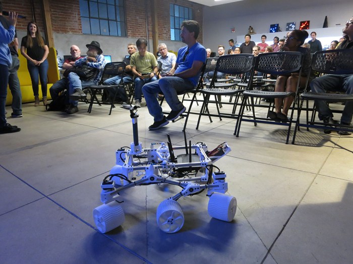
I brought Sawppy the Rover to the June 2018 meet for Hackaday Los Angeles. As is typical of these events, there were two scheduled speakers who gave half-hour talks then the floor opens for anyone present to do a quick 2-minute “Lightning Talk”. I presented Sawppy the Rover to the Hackaday LA audience.
I remember the first time I signed up to do a Lightning Talk months ago and was horribly nervous. I still get nervous when it came time to hold the microphone and speak to the crowd, but it gets a little bit easier every time I do it. I really appreciate the opportunity to practice public speaking in little 2-minute chunks.
The audience seemed to really like Sawppy. When I started driving my rover down the center isle between the chairs, a lot of cell phone cameras came out to take quick snaps. Several people came up to ask for more details afterwards during the socializing session, including Jacob who just bought a book that’s all about Curiosity and is at least as big of a fan of the Mars rovers as I am. Jacob says he wants to build a Sawppy of his own, and I said I’m happy to help his efforts. There was also a little boy who seemed to be around 7 years old, asking questions about Sawppy that were far more sophisticated than I had expected of that age. I was definitely impressed.
At least one of those cell phone pictures has already made it online. It’s not exactly being internet famous but I’ll happily take it!
The story told so far of Sawppy the Rover is about its development and construction, and that story has reached the point where Sawppy is running into shortcomings of PLA plastic. The next step in that story is to look into rebuilding Sawppy in PETG plastic, but before we take that step, I’m going to rewind a bit and tell a different aspect of the story.
The story of the 3D printers behind the rover parts.
A very deliberate design goal for Sawppy is for it to be accessible to interested builders who don’t have a high end expensive 3D printer. Designing to be printable on low-end machines means avoiding printing parts that demand tight tolerances, so Sawppy uses pre-made gears and bearings instead of printing them. I’ve been pretty happy with my Monoprice Maker Ultimate (Wanhao Duplicator i6) but I know it is a few steps up from entry level. To make sure Sawppy can be printed on entry level machines, the best thing is to buy one and use it to print Sawppy.
So off we go to Monoprice.com to buy an open-box Maker Select (Wanhao Duplicator i3) which is one of the most affordable Prusa i3 clones available on the market. There are cheaper printer kits, but ready-built printers don’t come much cheaper than these either in price or quality.
This is actually my second go at one of these printers. I had purchased a new (not open-box) Maker Select before as a relative 3D printing beginner and it printed well for a month. But a few days out of the 30-day satisfaction guarantee period, the control box started filling the room with smoke of burnt electronics and it never powered on again. I returned that machine under the 1-year warranty and used the store credit towards the Maker Ultimate I have now.
This time around, in exchange for the open-box discount, I fully expect a problematic printer. People don’t return 3D printers for no reason, so it’ll be a complete luck of the draw on the particular…. personality… of an open-box 3D printer. And this time around, with a year of 3D printing under my belt, I hope to better able to deal with printer issues.
I expected an adventure, and I got one! This is the story of an open-box printer that was (eventually) able to print PETG parts for Sawppy the Rover version 1.0.
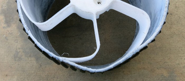
Sawppy tearing up its right-front steering coupler was the most obvious attrition from spending a day showing off to JPL employees. There was another problem less visible to casual onlookers: Sawppy’s wheels were slowly deforming under the southern California sun. By the end of the day, some of the wheels were decidedly out of round.
The 3D printers that printed Sawppy’s parts were loaded with Monoprice’s PLA plastic filament. PLA plastic is relatively cheap, easy to print, and rigid which makes the material good for prototyping mechanical components. Part of why it is easy to print is that it is easy for the print head to melt the material for extrusion then quickly solidifies into the proper shape. The downside of this “easy to melt” behavior is that it doesn’t take a lot of heat before PLA plastic softens. Sawppy’s thin delicate wheels couldn’t hold their shape after spending a few hours on sun-heated concrete and asphalt.
Earlier tests indicated the rigidity – and corresponding brittleness – was a weakness of printing these wheels in PLA. Now we can add lack of temperature tolerance to the list. It was not surprising but still mildly disappointing to see PLA distort.
Given this experience with brittleness and deformation under summer sun, we have motivation to look into a more ductile plastic material that is less likely to deform in the summer. The first candidate is ABS plastic, which I’ve tried to print before without much success. The second candidate is MatterHackers PETG, which is a favorite among local makers.
During JPL’s IT Expo, Sawppy was on display and roaming around. Partway during the day, when setting up for a photo shoot, a shaft coupler tore out of Sawppy’s right-front steering servo. This was embarrassing and Sawppy limped along with some field repairs until the end of the day when we could analyze its failure and devise a path forward for all of Sawppy’s servos, not just the front-right wheel steering that failed.
On that day, the baseline JPL Open Source Rover was on display but was not driving because one of the steering couplers had failed on an earlier JPL outreach event and has yet to be repaired. Which wheel failed? The right-front wheel.
Even earlier – when the SGVHAK rover was just about to make its debut at SCaLE, a test drive session damaged the gearbox in one of the steering mechanisms. This required a short-term servo hack to get the rover back up and running in time for SCaLE. Which wheel was damaged and needed the hack? The right-front wheel.
There are likely some perfectly logical explanations for why this might happen, but to the irrational human mind, such stories are where superstitions are born.
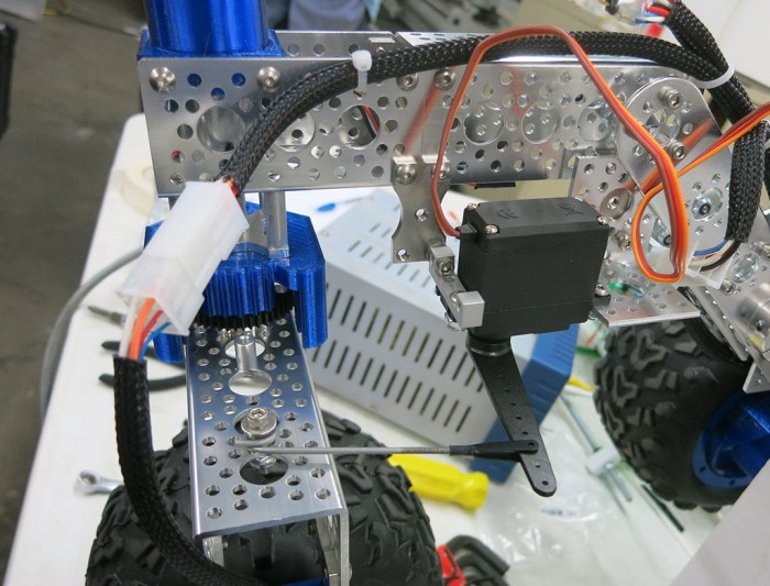
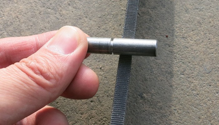
Sawppy the Rover’s steel shaft upgrade for bigger flatter detents, along with applying thread locking compound to set screws, was the final task completed before it was time to go visit JPL. Since Sawppy will be running throughout the day, I expected that the next weakest point in the system will surface. And indeed one did! The winner of “next weakest link in the chain” is the shaft coupler holding the servo horn to the steel shaft.
The coupler was 3D-printed and designed around the LewanSoul LX-16A servo and the servo horn mounting screws that came in its package. LewanSoul products using these servos are made of thin sheet metal, so these screws are very short. In fact they are exactly as long as the servo horn is thick, possibly to ensure that it’s impossible to accidentally fasten the servo horn into the servo body.
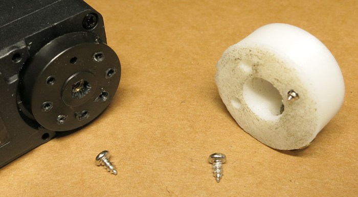
Unfortunately, what this also means is that when used to fasten a 3D-printed plastic part, there is not enough thread engagement for a good grip. So when one of Sawppy’s corner steering is over-stressed, the screws tore out of the servo horn.
This particular coupler design only used three screws. I tried to perform a field repair by fastening into alternate holes on the horn but that quickly tore out as well. By the end of the day we have this mess: a servo horn where every hole is damaged.
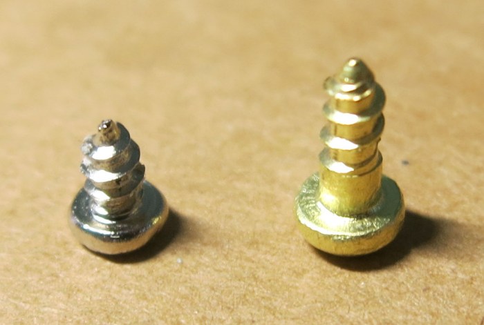
It’s clear that to accomodate a 3D-printed shaft coupler, we can’t rely on the short screws that came in the servo package. We’ll have to upgrade to something longer and these screws (McMaster-Carr catalogue item# 98685A220) look like good candidates.
After roaming the backyard and other terrain over several days, the weakest part of Sawppy has been uncovered: the set screws holding couplers onto our steel motor shafts are losing their grip. A few of them are sliding off their designated positions, some of them are backing out.
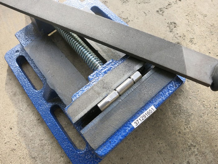
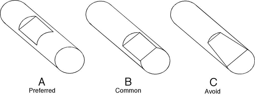
The set screw detents on the shaft were made by passing a Dremel cutting wheel over the shaft as described earlier, and now we have first hand evidence that’s not good enough. We need to make the detents wider and flatter. Something closer to what’s described here. This isn’t a job for a Dremel cutting wheel, as a wheel has a circular cutting profile. What we need is something nice and flat and can bite into metal, like a file.
The first attempt to make bigger detents were holding the shaft by hand and running it back and forth over the file. This was not working. Finger strength isn’t good enough to hold shaft at constant angle, so instead of a flat surface we ended up with rounded surfaces.
The second attempt brought a vise into the picture and flipped the arrangement around. Vise jaws hold the shaft, and hands hold the file. This delivered much better results.
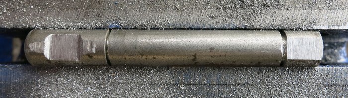
Here’s a set of before/after pictures. First the “before” image showing shallow and inconsistent detents cut with Dremel tool. Visible within them are circular indentations made by set screws – this particular pair of set screws had not yet started slipping and now we’re making sure they never will.
And the same shaft, after using the metal file to cut flatter and deeper indents:
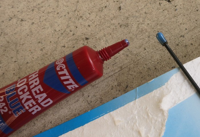
That was part 1 of the solution. Part 2 is to apply thread locking compound to our set screws. Loctite 242 was available at the local home improvement store.
If this isn’t good enough, we’ll upgrade to the more expensive Loctite 243 available at the local automotive parts store. According to the Loctite thread locker guide, 243 has a higher breakaway torque of 180 lb-in as compared to 110 lb-in for Loctite 242.
Before we do that, though, it’s worth running Sawppy around for a while to see what the next weakest point is. After bigger flatter detents and applying thread locker, the weakest point is probably not the set screws anymore.
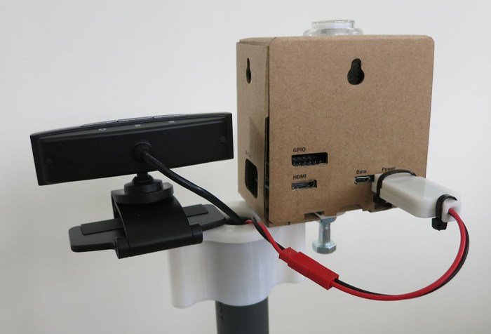
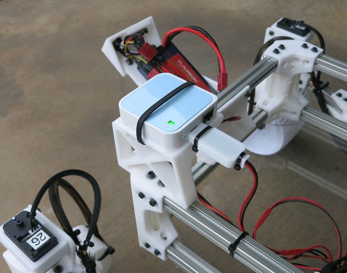
The Google AIY Vision box installed atop the camera mast is mostly for looks and, once powered up, will run its own “Joy Detector” demo independently of the rest of the rover. Once physical mounting and electrical power for the box was done, attention returned to the webcam.
As a first step, the easiest thing to do is to attach it to the Raspberry Pi 3 sitting in the rover chassis via USB. This is never going to be the long-term solution. For remote operation, a Raspberry Pi 3 doesn’t have the grunt to do a good job at real-time video compression and streaming. For autonomous operation, a Raspberry Pi 3 doesn’t have the grunt to do a good job at image recognition and analysis. We hope the AIY Vision box can handle the latter role in the future, but that’s not where things are now. At the moment Sawppy is strictly a real-time remotely operated rover and what we want is live video.
One solution is to use a webcam that has onboard h.264 video compression hardware. Such cameras exist, but they are pricy, and getting the video stream out of the camera without its dedicated Windows software can get tricky.
The alternative is to sacrifice bandwidth efficiency to get a quick solution. It is relatively straightforward to pull individual frames out of a webcam in the form of JPEG still images, and it is computationally trivial to send them one after another in rapid succession to create a Motion-JPEG video stream.
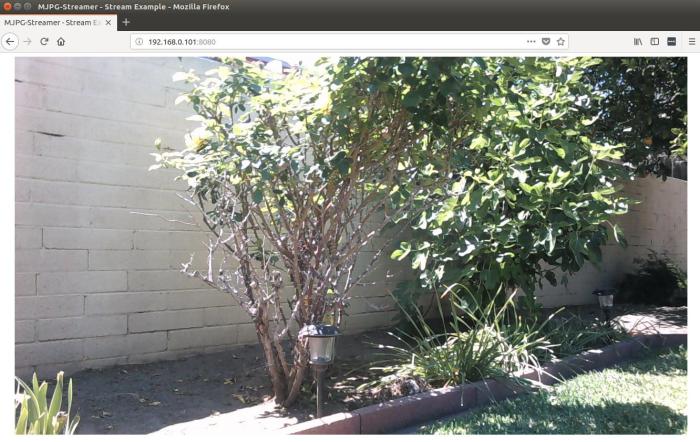
It took less than an hour to get basic camera operation up and running on mjpg-streamer thanks to these instructions. We have a video stream that is crystal clear and we are not straining the Raspberry Pi 3 processor to do it. We are, however, putting a load on the wireless network because the 1280×720 Motion-JPEG video stream takes up about 30 megabits per second (mbps) of bandwidth. This is a tremendous bandwidth hog when considering Netflix can deliver full 1920×1080 high-definition video in less than 5 mbps.
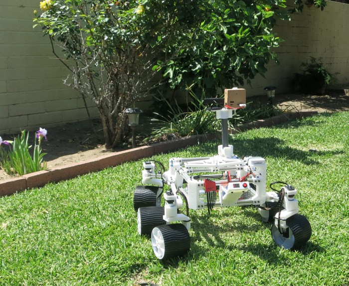
But that’s something to be addressed later. In the meantime, it’s time for Sawppy to roam the backyard!
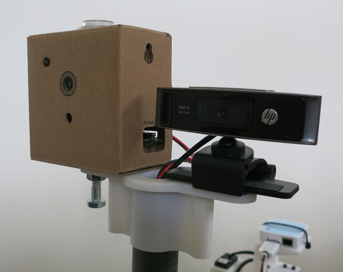
With a crude but functional folding base for the mast installed, attention turns to the camera to be installed at the top of that mast. Mars rover Curiosity has an extensive sensor array on top of its mast, but at the moment we only have a HP HD 4310 webcam and frankly, it looks a little sad and lonely atop that camera mast. It certainly fails to present a profile reminiscent of Curiosity’s array. What to do?
Add another camera! And not just any camera, one of the most intriguing device to be widely available: the Google AIY Vision kit. I picked it up because it seems like a cool way to get started playing with Google’s neural network software development resources. It’s pretty amazing that something I can pick up at my local Target incorporates a programmable neural net processor. What an exciting time to play with technology.
But that’s still on the to-do list. Until them, this AIY Vision box is only running the default out of the box “Joy Detector” demo. It’s not clear if the capabilities of this vision processor would even overlap with anything that’ll actually be useful for an autonomous rover. In the meantime I shall express my optimism by bolting the box onto the camera mast alongside the webcam. Now the top of the mast looks better, with proportions more closely analogous to Curiosity.
Although the vision processor only has the default demo, I still thought it would be fun to have it up and running. Even if it’s not helping the rover understand its world (yet). Since the general-purpose computing portion of the kit is a commodity Raspberry Pi Zero WH device, we could build another microUSB 5V regulator module to power it.
Now Sawppy the Rover can join the ranks of projects that incorporate an AIY Vision kit, with plans to make it do more, but just running the default “Joy Detector” demo for now. Like this cool owl perched on your shoulder and this robot dog.
The tallest object on Mars rover Curiosity is a camera and sensor array mounted on top of a mast. During Curiosity’s journey from Earth to Mars, this mast was folded down for transport. As a motorized model of the rover, Sawppy will also feature a sensor-topped mast. And while packaging constraints aren’t as strict for a hobbyist rover model, it would still be very convenient to fold the mast for transport.
As a simple first draft, we’ll have a fixed non-folding mount for the camera mast, which is a piece of PVC pipe. This will serve as the fallback solution. If Sawppy doesn’t get an elegant folding solution, I could at least pull the PVC out of this non-folding mount for transport.
With a fallback in place, let’s set goals of this project:
Use PVC pipe for mast structure.
Hollow center to run wires.
Fold and unfold without use of tools.
For sake of camera image, mast must be stable when raised.
Stability less important when mast is lowered.
Leverage natural flexibility of plastic to hold movable things in position.
The last bullet point turned out to be more difficult than expected. Our world is full of plastic spring clips, and familiarity lead to an incorrect impression it would be easy. It actually takes a fine control over dimension tolerances to make a plastic clip that flexes to allow movement yet clips tightly for a stable position. We also need good control over surface finish to create a mast hinge that rotates smoothly. Both are within reach of hobbyist level 3D printer but it takes effort.
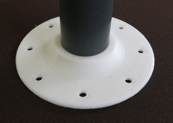
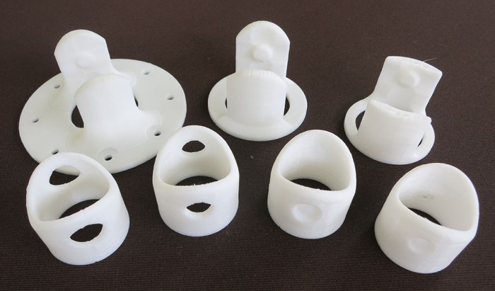
The first few iterations focused on a rigid cylindrical collar over the end of the PVC pipe, and a U-shaped mounting block on the body that clips onto that collar. The basic concept is for the U-shaped mounting block to have indents that favor two collar positions. Raised mast and 90-degrees rotated lowered mast. The U should be flexible enough to allow the collar to rotate between these two positions, but rigid enough to hold collar position once it reached one of the indents, plus a smooth surface finish so collar rotates well between the positions. This proved challenging and all of these iterations were either too stiff to be moved, or didn’t hold tightly enough after mast is deployed.
After these failures trying to make a mounting block that can balance rigidity and flexibility requirements, the requirements were split up to separate parts so each can focus on their job. The mounting block will focus on being rigid, and springy flexibility will be delivered by a separate external clip.
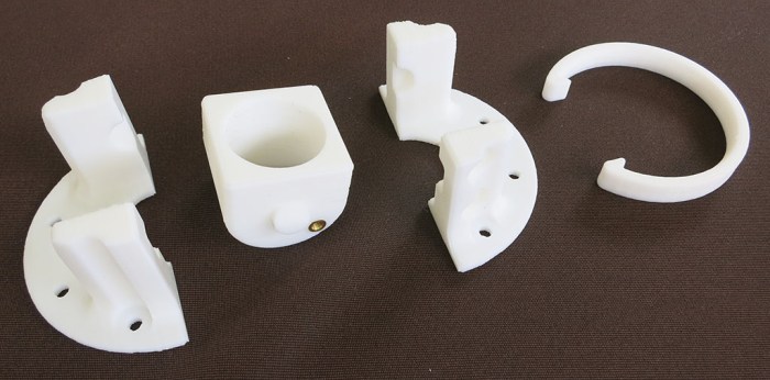
This second design also had a back-up provision for a screw to hold PVC collar in place. This would fail to meet the tool-less requirement but it didn’t take much effort to add to the experiment. It turns out the screw position had too little leverage to hold things in place anyway.
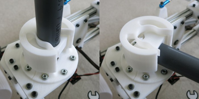
Since this mount block and PVC collar worked well enough to deliver rotational motion, design iteration focused on evolving the spring clip design. The clip got bulkier to help reinforce rigidity of the mounting block, but it also had a flexible clip for the PVC pipe placed so it had good leverage to hold the pipe in place without compromising the collar’s ability to reinforce the mounting block.
This is still really crude but it covers the basic functional requirements. It’ll be good enough for Sawppy’s first public appearance at JPL. In fact it was good enough to elicit delighted appreciation from a JPL engineer whose day job is running the real mastcam on Curiosity. Of course, she told me I should motorize my mast mechanism because her real mastcam does. Maybe in a future iteration! I definitely intend to put more effort into polishing this mechanism.
So far all of Sawppy tests have been performed as a client of a nearby wireless network. But we won’t always have a network to connect to. Sawppy may venture where we don’t have access privileges to a nearby network or possibly go places where there is no network at all.
This problem was encountered before on the SGVHAK rover project. The Raspberry Pi 3 on SGVHAK rover were modified to become its own wireless network access point by following directions posted on Raspberry Foundation website. The downside of Pi configured to be its own network is that we lose the ability to connect to the internet. This is probably a problem that can be solved by diving deeper into Linux networking configuration but there was also the problem of limited power of Raspberry Pi’s on-board wireless hardware.
As an experiment to reduce configuration headaches and to increase wireless power range, a TP-Link TL-WR802N mini router was added to the rover chassis. Now Sawppy the Rover has its own wireless network, giving us the following advantages:
We can use Raspberry Pi in its default configuration – no need to reconfigure Raspbian networking stack.
A wireless router is already designed to work to establish both (1) a standalone wireless network and simultaneously (2) have the ability to connect to an external wired network. Plug in an Ethernet cable and Sawppy is on the internet, no reconfiguration required.
A wireless router is already set up to be secure. TP-Link may or may not have covered all the bases, but it is expected to be more secure than a Raspberry Pi configured by a Linux networking amateur.
A dedicated wireless router has a more powerful wireless antenna.
Additional modules can be added to Sawppy and communicate over local wireless network. For example, adding a commodity wireless IP camera.
The mini router is mounted to a stand bolted above the rear right corner. This location was chosen because that’s where real Mars rover Curiosity’s UHF communications antenna is mounted. Power for this little router comes from a micro-USB cable, so we could power it with another unit of the same power converter used to power the Raspberry Pi.
The TL-WR802N is a nice compact solution that avoided having to mess with Raspbian (Linux) networking and, more importantly, the risk of doing it wrong. It was also more powerful than a Raspberry Pi’s on board wireless networking, but sadly not by as much as originally hoped.
Sometime in the future Sawppy will get a more powerful router for greater range, hopefully a dual-band unit to access the less crowded 5 GHz WiFi band. With more power and 5 GHz ability, Sawppy should have a better chance of tolerating noisy RF environments like SCaLE exhibit floor.
Up until this point, all the equipment inside Sawppy the Rover’s equipment bay has been installed onto the bay’s aluminum extrusion beams in an ad-hoc fashion. Sometimes they were zip-tied onto a beam, sometimes taped, and sometimes they sat on a small 3D-printed shelf. None of them were very robust and they all shared the problem they can be damaged by obstacles Sawppy is trying to climb over.
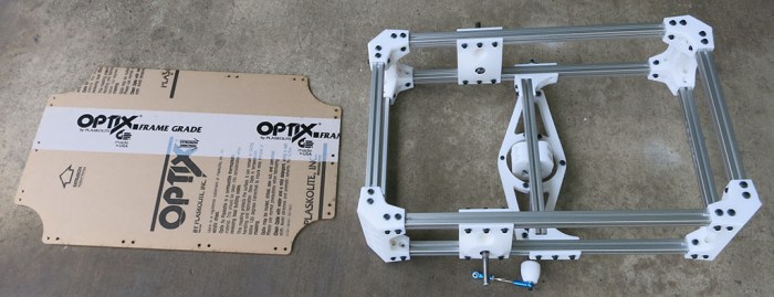
They were just temporary placeholder solutions until we could get access to a laser cutter to create a sheet of acrylic to serve as the bottom of Sawppy’s equipment bay. One was drawn up to match equipment bay dimensions in CAD and the file waited until laser cutter access was available.
Since the acrylic sheet’s dimensions came from CAD and not the actual box that has been built, it’s no surprise its installation exposed some assembly errors. This is a tale as old as engineering, made better (or worse) by CAD software. It fits in CAD!
Aside from overall dimension errors, there was also a problem caused by overlooking the room taken up by our M3 nut installation tool. Installation tool for panel wants to occupy the same physical space as installation tool for body corner. This doesn’t work very well in the real world. The real fix is to move fastener holes on the acrylic sheet. For now our workaround is to offset insertion tool and use only one of the M3 nuts.
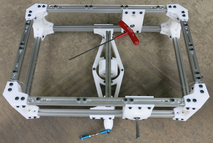
This first attempt fits well enough to proceed with Sawppy construction. Now we have a bottom panel to the equipment bay and components now have something nice to sit on.
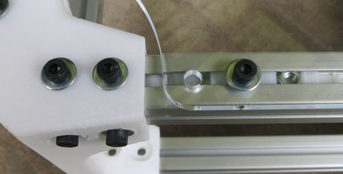
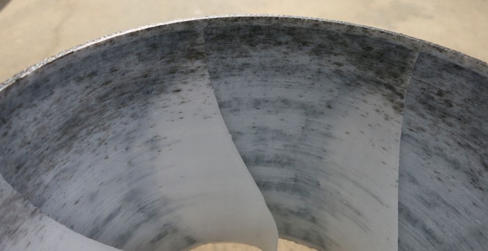
But we have one final problem for today: laser cutting a sheet of clear acrylic means it is very hard to photograph. This picture tries to draw attention to the clear sheet with a hex wrench placed on top of the sheet. The hex wrench is not floating in mid-air!
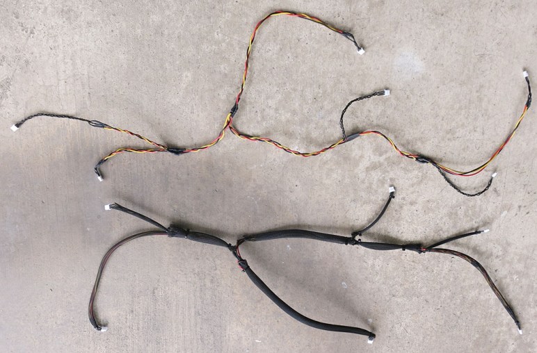
After wheel traction was improved by a coat of Plati-Dip, focus turns to the other problem exposed by initial climb tests: serial bus servo wiring harness. First we have the functional problem of wires dangling and risk getting caught on obstacles. There are three wires in the bundle and it only takes one snagged wire to stop the fun.
We also have an aesthetic problem with the bundle. It was obviously assembled by an amateur with ill-fitting joints and unsightly transitions. The original idea was that we could tuck our wiring harness inside these aluminum extrusion beam’s channels, but the poor soldering job meant the wiring bundles are now too fat to fit.
The most obvious solution is to use more zip-ties to hold wires closer to suspension components, but there’s a downside to be aware of: zip ties grabbing tightly on wiring insulation is not good. Too tight, and it will chafe on the insulation and possibly cause short circuits long term. What we desire is a way to hold the wires in place, but not too tightly, distribute the fastening stress across all three wires (instead of whichever one happens to be ‘outside’) and give them a tiny bit of room to move around to avoid chafing.
The answer to all of the above wishes is an expandable braided sleeve. Sawppy the Rover is certainly not the first to have a need for wire management, and there are a wide assortment of sleeve materials and designs to choose from. For a serious engineering project, we’ll need to evaluate the material’s mechanical properties, thermal tolerance, and chemical resistance. But since a little hobbyist rover isn’t picky about such things, we’re going with a cheap PET variant from Amazon (*). In this particular instance, something cheap is far better than nothing at all.
Here are the two wiring harnesses (one for each side of the rover) in the middle of this wire management project. On top is the ‘before’ picture showing all its chaotic awkwardness, and below is the ‘after’ where braided sleeves have almost completely masked all the flaws. And with the eyesore factor eliminated, we can put them back on Sawppy’s chassis.
(*) Disclosure: As an Amazon Associate I earn from qualifying purchases.
Plasti-Dip is a spray-on flexible coating that has found a niche of car customization, which was how I encountered the product and used to turn ideas into reality. One subset of Plasti-Dip users take advantage of its temporary spray-on peel-off status to customize their car’s wheels, sometimes changing them around as often as other people change fingernail colors. It’s common enough that dip is available in “wheel kits” tailored for the purpose.
For automotive wheel customization, the dip goes on the metal with the rubber tire masked off from dip. I’m going to dip Sawppy’s wheels but doing the reverse – putting dip all around the outside perimeter of the wheel and by doing so, give Sawppy the rubber tire that it current lacks. The motivation comes from the fact Sawppy’s climbing ability is currently traction-limited despite the grousers printed on the outside surface. Experimentation has proved that 3D-printed hard plastic wheels lack grip against certain obstacles that I’d like Sawppy to climb. There are several ideas on how to improve traction on these wheels, the easiest one to try first is Plasti-Dip as there are a few spray cans on hand from earlier car projects.
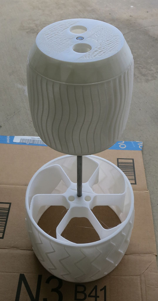
Again as a reversal from dipping car wheels, I’ll mask off the interior surfaces. I had hoped this will give a nifty two-tone appearance, white innards contrasting with the outer coat of black dip. To accomplish this without tedious masking tape work, wheel covers were designed and printed.
They are installed to either side of the wheel on a 8mm steel rod.
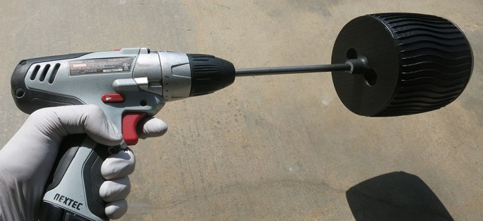
Plan A was to use an old rover wheel prototype as the base for a spray stand. This did not work as well as hoped because it meant the I had to move all around the stand in order to cover all sides of the wheel.
Plan B was to hold the steel rod and rotate it by hand during spraying. This dramatically reduced the effort but the results were uneven.
Plan C worked the best – install 8mm rod into cordless drill chuck, set the gearbox to “Low”, and use it to turn the wheel at a much more consistent rate, which directly translated to a much more consistent coating.
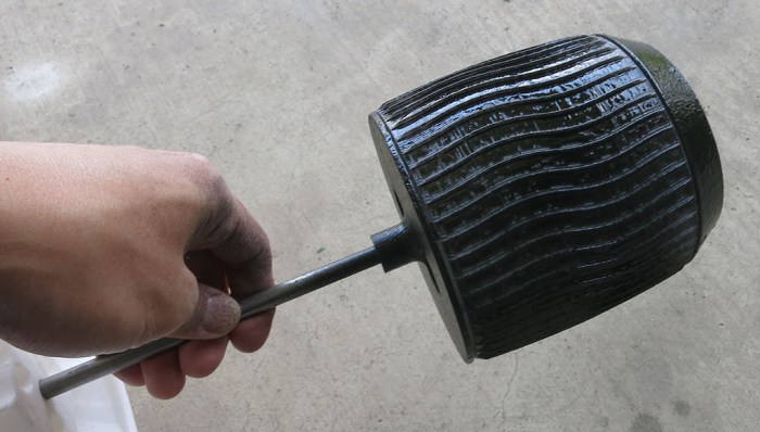
Sadly, all the effort spent on masking off the insides with wheel covers failed to deliver a crisp white/black contrast.
The first problem is a nature of 3D printing: gaps between layers are great at pulling liquids along with capillary action. Many of these gaps pulled liquid dip into various crevices between layers, resulting in an uneven coloration.
The second problem is user error. After a wheel was sprayed, it was set aside to dry and cure while the next wheel is sprayed. The smart thing to do would be to keep the wheels far away from the work area, or provide a divider, or at least make sure the work area is not upwind of the drying area. None of these occurred, which meant the white parts of the wheel now look really dirty thanks to overspray. Thanks to capillary action, a small droplet soaks in to make a big mess that is impossible to clean.
These are valuable lessons to remember if I try this again.
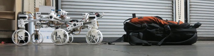
Once Sawppy received its new power system that could deliver the amperage necessary for challenging climbs, it was time to see what the rover can do. Here’s video footage of a particular test where it climbed a backpack.
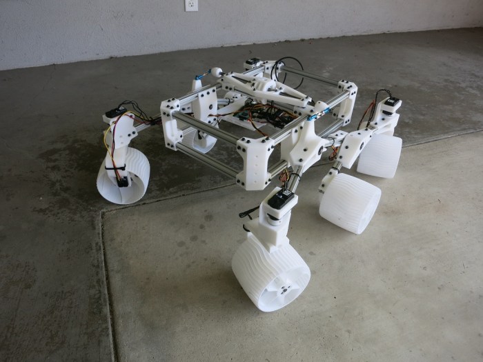
The most impressive part of this particular demonstration is the height of that backpack. At its highest point, the backpack was approximately double the diameter of Sawppy’s wheels. This was a little difficult to see from the angle of the above video, here’s a picture taken from a different angle.
Credit for this climbing ability goes to the rocker-bogie suspension geometry copied from real rovers JPL sent to Mars. It allows real rovers to roam a planet with no roads, and on this planet it allows little rover models to climb obstacles better than other wheeled vehicles of similar size.
While the suspension geometry is working marvelously, this series of climbing experiments exposed other limitations. Sometimes Sawppy’s servo motors do not have enough torque, and that is an understandable weakness of these $15 serial bus servos. Like we’ve said before: it’s a trade off for hitting its price target. Also, the wiring harnesses need to be better managed, it snagged on a few obstacles that the rover otherwise would have no problem climbing.
And lastly: grousers on these wheels only help in some situations. Sawppy’s climbing ability is frequently limited by lack of traction. The current design works well when there’s something for the grousers to grip – for example the rough texture of a backpack – but sometimes the grousers can’t find a feature to grip onto. This leaves us with the very limited friction of hard PLA plastic.
As an experiment to help Sawppy get a grip, we’ll try coating the wheel surfaces to see if we can improve traction.
Now that Sawppy has a big battery pack sticking out the back, the next task is to think about how to distribute that power to internal components. This is not yet a big problem in Sawppy’s current configuration because we only have two things right now: the Raspberry Pi and the serial bus servo controller. But since Sawppy has ambition to grow in sophistication, it’s worth thinking about the problem while it’s still easy.
With two components, Sawppy already has two different voltage level requirements. The Raspberry Pi 3 requires regulated 5 volts up to 2.5 amps though fortunately that’s a problem with a known solution. The serial bus servos may draw up to 1 amp each. With ten of them on board, the potential maximum draw would exceed the capability of the voltage regulator used for the Pi. Fortunately the servos are OK with direct 2-cell lithium cell power so there’s no need to find a beefy voltage regulator.
One solution for rover power is to create a master power supply module that can regulate and deliver power required by each component. But at this point in Sawppy’s evolution, it’s too early to know what components never mind what power they want. It’s better to go with a distributed system where raw battery power is sent out and each endpoint is responsible for its own power regulation. This will mean lots of duplication, but it also offers freedom to swap things in and out for experimentation.
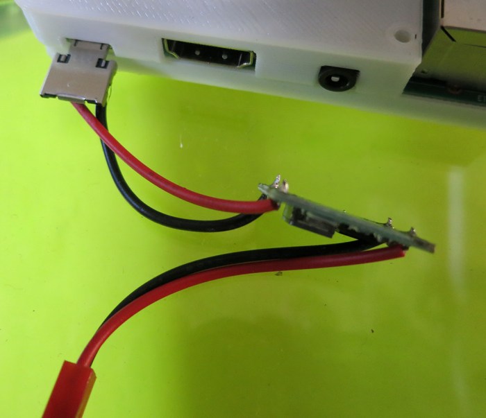
For the moment, that means the existing solution for Raspberry Pi will be used. That solves the electrical problem but physical robustness leaves something to be desired. We can’t leave wires dangling by their solder joints!
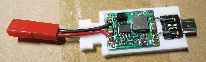
A 3D-printed enclosure was designed to hold both the step-down voltage converter and the micro-USB plug used to interface with the Raspberry Pi. They are now connected by a short segment of rigid wire, eliminating movement and a potential point of failure. Power input wires for the voltage converter now have a little bit of help against physical forces from the enclosure. It’s not full and proper strain relief but it’s a start.
The two halves of the enclosure are held with zip-ties. Again, not a full and proper solution but much better than dangling wires and bare circuit boards. It’ll be good enough while Sawppy evolves.
Once we had our first powered test drive (hooray!) It was time to address the most obvious problem it unveiled: the power supply. The test had used a small 2-cell lithium polymer battery pack that was over ten years old. Originally purchased for small lightweight remote-control aircraft, its capacity has diminished over time as lithium chemistry battery cells tend to do. Sawppy will need a higher capacity battery pack.
Remote control aircraft battery packs like the old unit on hand tend to be small, lightweight, and correspondingly expensive. Fortunately there is another remote control hobby niche that is less weight-sensitive and has power consumption profile nearly identical to Sawppy: remote-control off-road vehicles. The 1/10th scale monster truck category seems to have standardized on using a pair of 2-cell lithium packs so that’s what I bought.
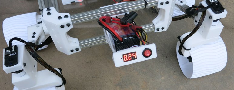
A few accessories were purchased alongside the battery. First a pack of power switches so Sawppy can be turned on and off more elegantly than reaching in and unplugging the battery. To protect the battery, we’ll want an always-on and visible volt meter to monitor its voltage. To protect the rover, we’ll add a fuse holder in line with the battery and a variety pack of fuses. The battery pack is advertised to deliver up to 30C which is far more than any Sawppy component would want (or can tolerate.) Hence a fuse to cut power if there should be an unfortunate short-circuit.
Once all the parts were on hand, the next decision is where to put them all. Since Sawppy is intended to be a mechanically faithful model of actual Mars rovers, the answer is obvious: we’ll put our power system in the back, sticking out at an angle just like real rovers have their radioisotope thermoelectric generator (RTG). Sometime down the line we might print a cosmetic cover that makes it look more like the actual RTG, but for now we’ll settle for matching its position and orientation.
Disclosure: As an Amazon Associate I earn from qualifying purchases.
Once the serial bus servo wiring harness was soldered (twice, once for each side) they were examined with a multi meter for obvious mistakes: First to make sure there’s continuity across all the terminals that are supposed to be connected, and make sure the bits that are supposed to be separate are indeed independent. After that was verified, it was time to hook everything up and try it for real. All we needed was a Raspberry Pi 3 to run SGVHAK rover’s software (modified to command Sawppy’s serial bus servos) and finding an old two-cell lithium ion battery pack to power it all.
Once everything powered up, the rover could move but in a haphazard uncoordinated fashion because the steerable wheels weren’t pointing in the correct directions. Before it can move well, we needed to find and record their actual center position. In theory there shouldn’t be any work necessary because a servo knows its center position and all we need to do is line up with it. In practice, each servo has a tiny bit of error, each 3D-printed shaft coupler has a little bit of error, etc. Overriding all these little errors is the fact these steel steering shafts were cut by hand on a poor man’s lathe so the set screw detents on either end of these shafts don’t line up at all. All these sources of error add up and they’re why we needed the ability to adjust steering center position.
Once center positions were established, Sawppy was able to roll around on its wheels. There was still a lot of work to do but it was exciting to cross this threshold.
The typical rule of thumb is that building your own computer from components is far cheaper than buying a prebuilt machine. Buying parts from Newegg.com, Amazon, Fry’s Electronics, etc. results in a better machine for less money than getting something from Dell. This was certainly true when I embarked on the Luggable PC project but a few notable events have since occurred to make an exception to the rule.
The blockchain fad is the biggest disruption. Cryptocurrency miners’ demand for graphics processors drove up their prices tremendously. At the beginning of my Luggable PC project, a NVIDIA 1060 card with 6 GB memory is considered a good mid-range GPU. (Or an entry-level unit for the more demanding world of virtual reality). A desktop 1060 video card was available for around $200 and I expected its price to drop as I designed and built my luggable PC. Instead, it spiked up to over $400 at times and is now hovering around $300.
The second disruption is in 3D-NAND flash memory. It is a big step change in price/performance so flash memory makers had no choice but to switch to 3D NAND technology or risk going out of business long-term. In the short-term, chip fabrication facilities have to be taken offline for this conversion, which meant a shortage of flash memory, 3D and otherwise, across the market. Driving up prices of solid state drives.
The third disruption is in DDR4 memory. There isn’t as clearly a single factor here but manufacturing capacity seems to be lagging market demand over the past year or so. Right now, DDR4 memory is nearly double the price of similar capacity DDR3 memory when historically they should be closer to price parity at this stage of technology maturity.
There are a few other factors at play, but the short-term trend is clear: many computer components have risen in price over the past year, counter to the long-term historical trend of ever-cheaper electronics.
Computer manufacturers like Dell deal in large quantities, and therefore they buy through supply contracts whose prices are independent of day-to-day market disruption. The upside of this approach is that, in times of supply shortages, Dell pays far less for their parts than market price.
Dell Inspiron 15 7000
Today’s example: a particular configuration of Dell Inspiron 15 7000 Gaming laptop is available for $750 after promotional discount codes. Let’s look at the components and the current (approximate) market price for their desktop counterparts.
NVIDIA GTX 1060 with 6GB: Admittedly the laptop variant of this GPU is slightly less capable than its desktop equivalent, but for the purposes of this comparison we’ll count it at the full $300.
Intel Core i5-7300HQ: Again this is a laptop-only part. It is similar to the desktop i5-7400 processor in that they both have a peak speed of 3.5 GHz, so $200.
256GB NVMe M.2 SSD: Unlike the other parts, desktop machines are happy to use the exact same M.2 form factor solid state drives using the NVMe interface. 256 is a little cramped but on a laptop it should be fine. (I stuck with 256 until the flash memory crunch eased a bit for me to upgrade to 512.) Let’s call it $100.
8GB DDR4 memory at 2400MHz: The smaller laptop-sized DDR4 modules are a little more expensive than their desktop counterparts, but we’ll round up to $100.
With these rough estimates, we’re already up to $700 and we’re still missing some major components necessary for a working computer.
Motherboard with M.2 SSD slot and built-in WiFi: Bottom of the line units are available for $70-80 but a reputable unit will be $100 and up. (It is the backbone of the system so not the best place to economize.)
Power supply: We can pinch a bit here, reliable though not super powerful units can be had for around $50.
Display: A 1920×1080 IPS monitor will be around $100.
Keyboard, Mouse, case (luggable or otherwise) and other miscellaneous parts: Round to $50 for a nice even tally.
That’s $1000 to build a desktop or luggable PC with similar specs as this $750 Dell laptop. And while the screen might be physically larger, the whole computer definitely won’t be as lightweight and portable. Such laptop-only traits – light weight, tight integration, ability to run on battery – usually demand a price premium over equivalent desktops.


