Spindle Clocks In At 11,100 RPM

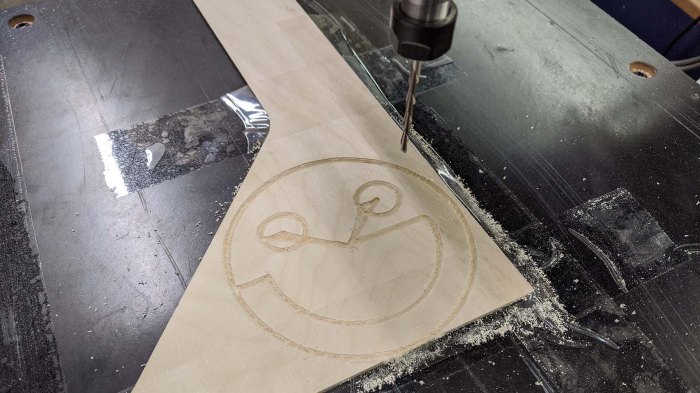
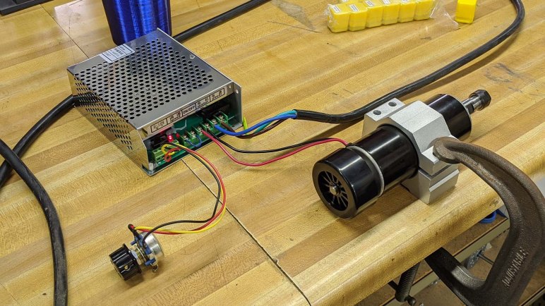
Once some convenience accessories are in hand, we return to the main business of cutting material. Our biggest unknown at this point is our spindle’s maximum speed measured in revolutions per minute (RPM). This is a critical part of calculating the “speeds and feeds” of machining. Yes, we’re cutting MDF which will be relatively forgiving, but the point of learning is to practice doing it right.

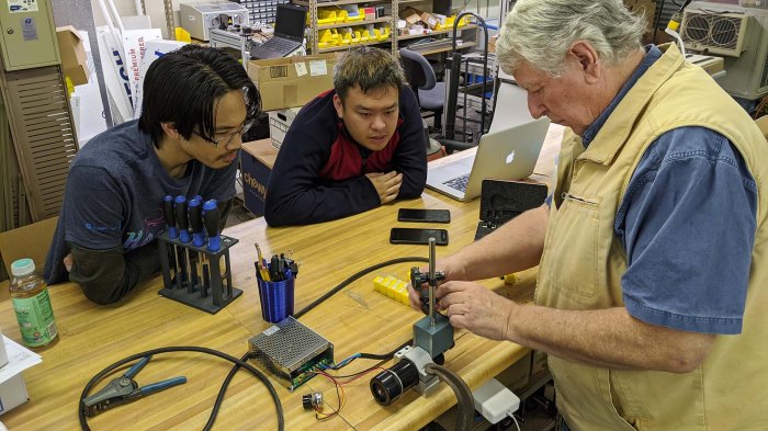
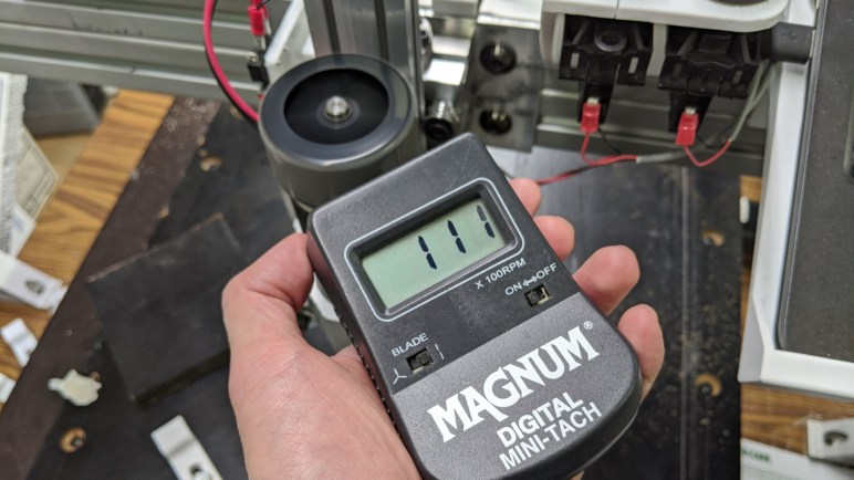
Our cheap ER11 spindle’s product page(*) claimed a maximum speed of 12,000 RPM, but we knew better than to take that at face value. To measure its actual performance, we wanted some sort of non-contact photo tachometer(*). This particular unit was on hand and originally designed for measuring remote control aircraft propeller speeds, and it measured the maximum speed at 11,100 RPM. We’ll use 11,000 RPM for our initial calculations. Later we’ll measure while it is cutting and see how much its speed drops.

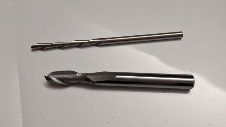
Is this fast? Well, “fast” is always a relative thing. Most people’s daily experience with RPM is on their car’s dashboard tachometer. In that context it is fast as 11,000 RPM is faster than most normal car engines, though race cars and motorcycle engines can hit that speed. For machine tool purposes, though, this speed is considered on the low side. Especially for small diameter tools that we’ll be using. Physically, we are limited by the small ER11 collet for our tool diameter. Plus the machine is not rigid enough to swing a big cutting tool without flexing. And now we know the limitations of spindle speed. Which of these limitations will be the one to actually constrain what we can do with the machine? Let’s have another cutting session and find out.


(*) Disclosure: As an Amazon Associate I earn from qualifying purchases.

Hex Wrench Holder And Wire Clip For Gantry Extrusion

The first project for designing accessories to mount on the extrusion beam, a holder for ER11 collets, turned out well enough I wanted to continue. Apply some of the lessons learned to create more nice-to-have accessories for the CNC project.

One accessory is a holder for a 5mm hex wrench. This is the size used by the fasteners bolting our gantry’s extrusion beams together. There are a set of four bolts, two on the left and two on the right, that we loosen to adjust the height of the gantry. Lowering the gantry lets the cutter cut through our work surface to cut holes for threaded inserts, raising the gantry gives us more Z travel for the work piece. Or we might deliberately trade off Z travel to use a shorter and more rigid gantry for more challenging pieces. We’re not sure what the viable combinations are, but we do know we’ll need this wrench handy for experimentation.

The other accessory is a wire management clip. Wiring is a perpetual challenge on this project, from finding appropriate component placement to isolating electrical noise. I’m sure electrical challenges will continue to vex us as we proceed. We’ll figure out the problems one by one as we go, but one thing is for sure, we’ll need a lot of ways to route wires and keep them in place, hence the clips.

Unlike the previous accessories, the wiring clip may be mounted in any orientation. To hold themselves in place, each clip will require additional holding force. To get this force, they are printed slightly more open than their installed configuration. Installation would then require compressing the ring and this tension in the plastic will provide friction against extrusion rail to hold it in place. And while I’m not entirely sure it will be necessary, I added a small flap to keep the wire from sliding out of the ring into the rail slot.

There will be more accessories along the lines of what’s been printed so far, but I’m eager to get back to the primary exploration of cutting material.

Collet Holder Clamps To Extrusion

While I was in Onshape CAD designing our goose neck work holding clamps, I also tackled a few other to-do items on the 3D-printable accessory list. The top of the list was building a way to keep extra collets accessible on the machine. Our CNC spindle came packaged with a 1/8″ ER11 collet, which we swapped out for a 1/4″ collet when we wanted a stouter cutter. We didn’t have a good place to keep the temporarily unused 1/8″ collet and, rolling around on the tabletop, we were constantly at risk of losing it.

I thought it was a good project to practice designing plastic’s flexibility to my advantage instead of constantly seeing it as a disadvantage. I’ve had several projects along these lines before, but my interest was renewed by Amy Qian’s demo board she brought to show off at Supercon.

There are two ways I wanted to apply this concept. First, I wanted a holding mechanism that can snap into an extrusion rail and stay there without use of tools or fasteners. Second, I wanted a way to hold the collet so that it is held securely by default (not fall out or be dropped easily) but can be removed easily on demand. Again without tools or fasteners.

Here is the first draft of a flexible clip for installation into extrusion beam, this design was too flexible and fell out of the extrusion rail easily. More iterations followed, hunting for the most secure hold possible while still making it possible to insert into the rail.

Extrusion slot clip

Separately, I started designing a flexible cover for the collet. The test piece for each mechanism evolved separately until I was happy with both designs, then they were integrated into a single piece incorporating both mechanisms.

Collet holder evolution

With the success of this holder, I took the lessons of a flexible extrusion beam mount and applied the concept to a few additional 3D printed accessories.

3D Printed Goose Neck Clamps For Work Holding

Once we have metal threads securely inserted into our MDF work surface, we could bolt on clamps to hold our work pieces. These clamps are 3D printed because we fully recognize our CNC beginner status and, while we’ll do our best to avoid crashing cutting bits into fixtures, it’s realistic to plan for the probability that crashes will occur despite our efforts. If we use commodity metal clamps and our carbide cutting tool makes contact it will break our tool. But if our carbide tool contacts a piece of 3D printed plastic it might survive our mistake. We have the luxury of this provision because we’re starting easy with scraps of MDF, which requires less forces to hold and to cut than cutting metal.

Clamp evolution

We started by copying standard step clamps. We weren’t sure if the steps could be accurately replicated with 3D printed plastic so it was worth a bit of experimentation to find out. They look very promising but we probably won’t use them, because the reason step clamps exist is to have a few set of them that can adjust to various sized work pieces. 3D printing gives us the flexibility to print project-specific fixtures that don’t have to compromise for flexibility. This advantage can make up a tiny bit of deficiency inherent in using plastic instead of metal. Hence the second iteration: a single piece clamp shaped like an L designed specifically for the thickness of our test piece of MDF.

Once that was printed and eyeballed on the work table, we moved on to the third iteration: a low profile goose neck clamp tailored for the height of our scrap MDF. Low profile design reduces chance of cutter collision, and it allows us to use shorter and stouter bolts to fasten them to the table. This is what we will use for our first real cutting experiments, alongside other 3D-printed accessories for our CNC project like a collet holder.

Threaded Insert Alignment Tool

We now have a small G-code program that we can call upon to cut holes for self-tapping threaded inserts. We’ll cut them as needed for work fixtures on our CNC work table. However, cutting the hole is only part of the process, we had to install the metal insert as well. In order for the resulting threaded hole to be vertical, the inserts have to be held perpendicular to the work surface as we install them. However, the coarse exterior thread makes it difficult to maintain the orientation, made more challenging by the fact the shallow hex socket allows the insert to rotate around the tip of a ball-end hex wrench making it even harder to hold vertical.

We originally had the hypothesis that, given the geometry of the wooden hole, our metal insert will self-align as we start turning it. This may be true for some types of wood but it didn’t work for our particular sheet of MDF. If the coarse outer self-tapping thread starts biting at a bad angle, the insert did not self adjust in our experience. It just jams partway down the hole ruining the MDF hole in the process.

To solve this problem, we designed a small 3D-printed plastic tool to help maintain vertical alignment for installation.

Insert alignment tool printed

The bottom part of this tool helps keep the insert vertical, and the top part keeps the hex wrench vertical. The bottom is mostly flat for the work table surface. I tried adding a small lip to help with hole alignment, but that turned out to be unnecessary. These metal insert can align itself in the XY plane well enough. And once these inserts are in place, we can bolt down our pieces of scrap MDF using custom gooseneck clamps.

CNC Test Program Prepares For Fixtures

My test program exposed an electrical noise issue and helped us track it down to the spindle motor. This was an unplanned but very welcome bonus result on top of its original purpose. It was my first foray into Autodesk Fusion 360 CAM module after following tutorials. I wanted a simple program with few operations, small enough for me to fully understand the G-code output from Fusion 360 post-processor for Grbl. We had scrap pieces of MDF on hand for practice cuts so it wasn’t important for the test program to do anything useful. But as I was contemplating work holding for scrap MDF, I realized my first program could be useful after all.

The work surface we installed earlier was also laminated MDF, cut from the same retired treadmill board as the test scraps. Its smooth (well, scratched up, but still relatively flat) top surface is not conducive to any kind of work holding. The original plan was to cut holes by hand with a cordless drill and fasten work pieces using bolts from above fastened by nuts from below the sheet.

Then we had a better idea – use threaded inserts. Counterpart to the heat-set inserts I’ve been using in my 3D printed plastic(*) projects like Sawppy, there are inserts available for wood.  They have a self-tapping coarse thread appropriate for wood on the outside, and a durable machine thread on the inside. Given that our XY table used mostly 1/4″-20 thread, we will continue the trend by using these inserts from McMaster-Carr.

All we needed to put these in was to drill a hole of the specified diameter, and this is a task I can have the machine do for its own work table. I first started with a single hole, walking through each line in the generated G-code to understand what’s going on. The results were fine for the insert itself, but the exterior thread damaged surrounding laminate surface during installation.

Inserts with cracked laminate

This lead to extension of the test program, adding a second cutting operation. The first one cut a hole all the way through the surface for the insert, and a second shallower cut to clear surrounding laminate to avoid damage by exterior tread. Once the metal insert was installed with help of an alignment tool, we have a clean fastening point to bolt work pieces to our machine work surface.


(*) Disclosure: As an Amazon Associate I earn from qualifying purchases.

Next Challenge For CNC: Electrical Noise

With a stouter cutter installed, we can experiment with less worry about breaking it. I started generating my own G-code programs from Autodesk Fusion 360 and testing them on the machine. (More about this test program later.) A safety practice I learned in my machining class is to test run a G-code program by intentionally setting a too-high Z offset. This way, when the machine runs through the program, it runs through all the motions but is only moving around in air. This lets us verify the range of motion is as expected. Including making sure it would not exceed either the XY limits of the machine or hit any hold down fixtures that are in the work space.

This process can be repeated any number of times, each time putting the Z a little closer to the workpiece than the last. And even if we don’t expect to actually cut material, it’s a good idea to power up the spindle just in case the cutter makes contact. While unexpected cuts in the work piece is not great, ramming a non-spinning cutter into the piece is worse.

Running in air is great for finding major problems, but minor issues aren’t always visible. It wasn’t until I cut into MDF that I found our latest problem: after the test program made its cut, its final position did not match expectations. Running the program again, we expected it to run through the same motion and not remove any new material, but it did. Checking the coordinate display on bCNC, we saw the machine believed itself to have returned to the same position after each run, counter to our physical evidence on hand. What happened?

To diagnose this issue, we tried eliminating individual variables from consideration. Running down the list of possibilities, from loose wires to loose fasteners. The key experiment was running the program without powering up the spindle, at which time all motion tracked as expected. (To protect the endmill from possible impact damage, it was removed from the collet for this test.)

This tells us the source of our unreliable motion was an electrically noisy spindle. A hypothesis is that it degraded our motor controllers’ ability to distinguish signal pulses from Grbl, but the precise mechanism is not important. Whatever it was, we need to better protect the system from spindle motor noise. And since every motor will affect nearby electronics to some degree, this is probably not just a consequence of using the lowest bidder on Amazon.

In the immediate term, what we can do for our machine is to make sure the chassis is securely grounded, reroute signal wires further away from the spindle motor subsystem, and add a capacitor across the motor wire terminals to filter some noise. This was not precision tuning, as we just clamped the grounding wire to our gantry and the capacitor was chosen for its voltage tolerance rather than a specific capacitance. Still, the two measures seemed to improve the situation enough to proceed. We know “clean up wiring” is still on our list of technical debt, but this kicks the can a little further down the road and let me return to my test program – cutting holes for work fixtures.

Stouter Cutting Tool For Exploring CNC

Our vertical mill CNC project is barely far along enough for us to run a simple G-code program, so there’s a lot we don’t yet understand about the machine’s capabilities. Pieced together from mostly salvaged parts, we don’t exactly have a reference manual we can check for the machine.

What’s clear from our first test is that it’s easy to accidentally get too aggressive with the machine. The most fragile part in the system is our 1/8″ RotoZip cutting tool. While we want to make sure to wear eye protection when running the machine, we still want to avoid breaking cutters and turning them into sharp high speed projectiles.

To reduce the odds of that happening, further machine testing will use the largest cutting tool we can. Quarter inch shank diameter is just about the widest we can accommodate with our ER11 collet, so I went looking for the shortest quarter inch square nose endmill I can find on Amazon with Prime delivery. (*) McMaster-Carr has higher quality cutters and a wider selection of endmills in general, but they would not have delivered in time for the next available machine work session so I traded off quality for speed.

This is a carbide tool with two flutes. Out of the box, all cutting surfaces looked satisfactorily sharp. Used properly, it should have no problem cutting into our scrap test pieces of MDF. And when used improperly, it should be far less likely to break than our 1/8″ diameter RotoZip cutter. It will serve as the (possibly sacrificial) learning cutter while we explore the rest of our machine, starting with an electrical noise problem.


(*) Disclosure: As an Amazon Associate I earn from qualifying purchases.

Scrap MDF Sheet As CNC Working Surface

Once its homing switch was moved to the correct position, our Z-axis is ready to go to work. However, it doesn’t have a surface to work on just yet. The XY table forming the heart of this project was originally designed for the purposes of optical inspection, which meant it has a big open space in the middle for cameras and similar optical instruments to see. Big open spaces are not conducive to CNC milling operations!

Fortunately, as part of its original design, this table does have precisely placed mounting points for other equipment. These holes were, in fact, used to bolt the X and Y modules together at right angles to each other. We’ll use these mounting points to install a work surface. For precision work, we want something rigid. Ideally something just as strong as the table elements, say maybe a half inch steel plate.

But for learning purposes, we don’t need anything so fancy. We just need a reasonably flat surface we can work with. Following the theme, we’re going to re-purpose something for the task. This time, it is the main backing board for a retired home treadmill. This piece of laminated MDF had been sitting outdoors for several years and used as a ramp for moving heavy things around. The smooth laminated surface really reduced friction! But it also meant the surfaces are scratched up, and there are signs of water damage at the non-laminated surfaces. Still, it was the biggest, flattest, and most expendable thing on hand for our machine. So it was cut up with [Emily]’s table saw then 12 holes drilled on a drill press. Counter-boring those holes allows the top working surface to remain clear. We’re not worried about the cutting tool hitting one of these fasteners — they are outside of range of motion — but it allows flexibility in workplace positioning.

For our first test, we used a scrap piece of wood left from a laser cutter project and a RotoZip cutting bit. The first programmed operation will be the same smiley face test program we used before we even had a Z-axis. Whose G-code, we have now learned, never moved Z-axis at all! There are only spindle on/off codes, likely designed for laser engraving. Which also explained the speed, which pushed the RotoZip bit too fast, bending it quite alarmingly until we turned up the spindle speed. It did all right, but until we get the machine dialed in, what we really should use is a stouter cutting tool.

CNC first programmed cut using Rotozip bit

Reposition CNC Z-Axis Homing Switch

Top of the CNC mill electrical work items list was making sure it had a functioning Emergency Stop button. Once that was completed, the next work item was the Z-axis homing switch. For a vertical mill, we want the Z-axis homing operation to take it to its highest position, furthest away from workpiece. This is reverse of many 3D printers, which home against the print bed. This is because 3D printers have the luxury of  starting from an empty print bed as a characteristic of additive manufacturing. A CNC vertical mill, representing subtractive manufacturing, could not make such an assumption since the workspace would have work fixtures and material stock.

Our initial Z-axis homing switch was appropriate for our initial orientation of the mechanism, allowing it to home to the top of its travel. But once it was flipped around, the homing switch is now sensing the bottom of its travel instead. We need to find another mounting position before we could have a good Z axis.

Z homing switch wrong end

This switch had the luxury of sitting next to the motor and conveniently sensing the approach of the carriage. Its height was sized to match the length of the motor ballscrew coupler, engaging the switch just before the carriage would run into the coupler.

This linear actuator have no convenient location to sense the other end of the range of motion. Since there was no coupler on the other side, a similar mechanism would subtract from valuable range of motion. We didn’t have a good place until we installed the spindle motor mount plate, whose top edge gave us an feature we could use to trigger the homing switch.

From that point, it was a matter of running through a few 3D prints to find the correct dimensions to trigger a homing switch while maximizing useful travel distance. Now our Z-axis homes against the top of its range of travel again, let’s give it an useful surface to work on.

CNC Physical Controls Panel V2

When I started to build a panel for physical control buttons, I had planned to use arcade console buttons. Big, bright, and durable, they were designed to take a punishment and I thought they would serve well. But before I finished the first version, I had switched to a more task specific button for the emergency stop. I proceeded with arcade buttons for the other two, but [Emily] had a better idea.

She had salvaged some control buttons from retired industrial machinery, so these would be buttons originally designed for the purpose of machinery and not controlling a video game character. They should be given a second life doing their old jobs on a new pieced-together CNC vertical mill.

Salvaged switches for hardware buttons

Using them would require designing and printing another panel. They were smaller in diameter so I thought maybe I could get away with a shim, but even though their smaller diameter required less panel front surface, their mechanism for disassembly and installation actually required more clearance under the panel. As a result I had to rearrange the buttons from forward-back to side-by-side. This is a good thing – the results more closely mimicked that seen on real industrial equipment like this Haas console. My three-button panel is a poor comparison to that full featured beast, but is a lot cheaper.

I also appreciate the black rim on these buttons, making them more difficult to press them accidentally compared to arcade buttons lacking such protection. It was also interesting to note these buttons have provision for three switches underneath, controlling three circuits at once. These, however, only have a single switch in the center slot and given these were salvaged we are unlikely to populate the remaining two slots.

I started the physical button control panel task planning to use three arcade buttons I had on hand. By the time I completed the second version of the panel, no arcade buttons were used but the panel looked better and worked closer to the way they would be on actual machinery. I call that a success, and turned my attention to the Z-axis homing switch.

CNC Physical Controls Panel V1

Our mini CNC vertical mill project now has almost all the basic mechanical components in place. We’ve done a quick drill test, but that was under manual control. There still several very important things to add before we let the machine run G-code, the top of the list is an “emergency stop” button for when things don’t go according to plan. It would also be nice to have physical buttons for “cycle start” and “feed hold”, but that is less critical. I soldered some headers earlier in preparation for this, now I need to connect them to physical buttons.

I originally planned to reuse some arcade console buttons I already had on hand, but then realized there is existing convention for emergency stop buttons: once pushed, they stayed pushed until twist to release. They also have a distinct appearance everyone (not just myself) would recognize, and these are things I want to have on my own machine. I bought the cheapest one I found on Amazon (*) and the tactile feel of this unit definitely reflected its low price. If I were to do this again I’d hunt for a more substantial-feeling (and more expensive) alternative. But in the meantime, it seems to work well enough electrically and the low budget nature matches the rest of the project.

For the “Cycle Start” and “Feed Hold” buttons, I continued with the original plan of reusing arcade buttons I had on hand. I have a nice red one for “Feed Hold” but I didn’t have a green one for “Cycle Start”. I used a yellow one in the meantime, maybe I’ll paint it green later.

Then I designed and started printing a panel for these buttons, paying special attention to the emergency stop button’s support structure. I want people to be able to slam on this button hard in a panic without breaking anything. Unfortunately, due to an uncooperative 3D printer, I couldn’t get a finished print of the panel in time for a work session.

Hardware buttons panel - partial

No matter, it was enough for me to begin the wiring work for this project. Obviously I couldn’t mount the buttons on the machine until I returned later with a completely printed panel in another session. However, even as I was wrapping up this panel for physical buttons, we were already talking about an upgrade.


(*) Disclosure: As an Amazon Associate I earn from qualifying purchases.

CNC Spindle Mounting Plate

Once our new CNC spindle passed initial inspection, it was time to get to work mounting it to our Z-axis linear actuator. Again, the piecemeal nature of this machine meant the parts would not bolt up directly so we’ll need to fabricate another adapter plate. This meant cutting another piece off of the same 1/8″ aluminum stock used to mount the Z-axis on our gantry and marking up the dimensions we’d need.

Four holes were drilled to line up with the actuator extrusion beam, and four more drilled to line up with the motor mounting block that was part of the spindle package. The original plans were to use bolts and nuts across the board, but there was a problem with clearance: the motor mounting holes were almost exactly the width of the Z-axis rollers, leaving insufficient clearance for either M6 nut or bolt head.

The obvious solution was to tap M6 threads into the aluminum, avoiding the need for nuts and associated clearance. Unfortunately we had no M6 taps on hand, but [Emily] the resourceful improviser had a trick up her sleeve: We had plenty of M6 steel bolts, and we wanted to tap aluminum. Steel is harder than aluminum, and so with some modifications with the grinder, she turned one of the M6 bolts into a functional M6 tap.

Cheap spindle mounting plate creative tapping

Bolting directly into newly tapped aluminum, our M6 bolts would still just barely scrape the Z-axis roller assembly. Switching to thicker washers gave us the spacing needed to clear the rollers, allowing the spindle to move across the entire range of motion on our Z-axis.

Cheap spindle mounting plate installed

As a quick test, we mounted an 1/8″ drill bit into the spindle and performed the ceremonial first cut of this machine. I was moving the Z-axis via manual jog controls in bCNC, we still have a few more things to take care of before running this machine under automated program control.

Examining Air Cooled ER11 CNC Spindle

Up until this point, almost everything in the home brew vertical mill CNC project has been salvaged or reused from some previous project. But we’ve come to the point where the Z-axis drive has been properly configured for a spindle motor… that we don’t have. We have smaller lighter motors that aren’t strong enough for the job, we have big beefy motors too heavy for our gantry. While we could potentially use a Dremel or a RotoZip as a stepping stone, the decision was made to buy a cheap milling/engraving spindle from Amazon (*) for the project.

The product page proclaims a maximum of 500 Watts and maximum speed of 12,000 revolutions per minute. We’ll measure power draw once we can put it to work, and we have tachometers to measure its speed range. We don’t expect it to actually hit those numbers, but they seemed reasonable. The part that we were most skeptical about was the proclaimed precision: 0.01-0.03 mm of runout. This is a very high level that we doubted was reasonable in this price range.

The first test after unpacking all components was the obvious basic test: does it spin up? Once we established that it does indeed turn, the second test was then to mount a Starrett dial test indicator (*) to measure its actual runout.

Cheap spindle on Amazon getting dial indicator

The results were… surprisingly good! When the motor is not under stress and turning freely, it actually stayed within a very tight range. This specific dial test indicator was in Imperial units, measuring a range within +/- 0.0005 inch. This is in the ballpark of +/- 0.0127 mm, so the product listing was not a complete lie.

For practical purposes, though, we’ll never have that level of accuracy. There is a lot of flex in the system — from the motor output shaft to ER11 collet — to take us out of that range. A single finger press was enough to bend things beyond the technically-not-wrong runout, so we shouldn’t expect very high precision from this spindle after we mount it on our Z-axis and run under real cutting forces.


(*) Disclosure: As an Amazon Associate I earn from qualifying purchases.

Turn That Z-Axis Mechanism Around

Fourth iteration of Z-Axis was mounted expediently for the pen plotter test, where we found the ball screw was bent but everything else looked good enough to proceed. Following that success, I will make a better mount for this linear actuator to solve some problems with the quick test configuration we had used.

Zv4 mounted by vertical extrusion with old bracket

Problem #1: the test mount was a 3D printed plastic bracket. The best thing that can be said about the rigidity of the mount was that it is better than tape.

Problem #2: old mount leaves long Z-axis mechanism in place, moving the small carriage. Fine for plotters, but for a small vertical CNC mill we want the Z-axis mechanism to move out of the way of the work piece. This means flipping the mechanism around, mounting it by the small carriage so motor moves the entire assembly out of the way.

Zv4 aluminum mounting board in progress

A scrap piece of aluminum was drafted for this purpose. Holes were drilled by hand for fasteners. The accuracy leaves something to be desired, but the hope is that the machine will eventually get to a point where it can make a superior replacement for itself.

Zv4 aluminum mounting board almost ready

Because the carriage aluminum extrusion beam does not have the same spacing as the gantry aluminum extrusion beam, this plate allows us to bolt them together. Here it is almost ready for installation.

Zv4 mounted by aluminum sheet

Installation complete. Now when the tool moves up, the rest of the Z-axis moves up and out of the way with it. It is now ready for a CNC spindle.

Plotter Test With New Z-Axis Exposed Screw As Bent

One of the reasons I didn’t design and print yet another iteration of the pen holder was that I thought it was more important to design and print a mounting bracket for the Z-axis stepper motor. Up until this point, the stepper controller module was merely taped to the gantry. This was never going to be an acceptable long term solution.

Stepper driver - tape mounted

Once the stepper driver was mounted with a proper bracket and tested with the Z-Axis version 3, we removed Zv3 and installed Zv4 in its place. Complete with simple homing switch and parallel link pen holder. For this first test Zv4 was held with the same 3D-printed bracket used in Zv3, though that is already on the list for replacement.

After the fourth Z-axis assembly was installed, I loaded and ran the Sawppy portrait program used for testing the third Z-axis assembly. The Y-axis flex really messed up the plot far more than originally expected.

After watching the thing mangling a Sawppy wheel, I stopped the test. There was no point in going further. Here’s Sawppy wheel drawn by fixed mount for comparison.

Sawppy portrait result of flexible pen holder

But a beautiful pen plotter was never the point of the exercise. Making the machine act as a pen plotter was merely a way for us to visually confirm that the Z-axis is moving more-or-less in sync with the rest of the machine. So as poor as the new pen plot is, the main objective was accomplished.

The test did, however, uncover a problem with the salvaged Z-axis: the ball screw is bent. Now that it is under computer control we can run it at a consistent speed (better than turning it by hand) and now we can feel a small but definite wobble in the carriage. This would explain why it was retired! This wobble was evidently too much for its previous owner, but it’s still too early for us to give up on it. It is possible the wobble won’t be the biggest source of inaccuracy in this pieced-together CNC mill, and even if it is, we’ve established that this is a common and affordable form factor we can easily replace.

Therefore, we shall leave Z-axis version 4 in place and continue working on the rest of the machine until the wobble proves to be a problem.

Parallel Link Pen Holder Only a Minor Improvement

Abandoning rubber band flexible mechanism as too weak, I started thinking about using the 3D printed plastic itself as the compliance mechanism. I’ve long lamented about the lack of rigidity in 3D printed plastic, now is my chance to turn that flexibility to my advantage. Thus was born the second pen holder iteration, using two printed plastic links in parallel to keep the pen vertical.

Most of the thought went into how to print these links so that they could move independent from the underlying base. I toyed with the idea of printing support structures, or have them hang in air and take my chances, before I realized I could take another long-standing headache of 3D printing and turn it to my advantage. The weakest part of a 3D print are the bonds between layers. When a part starts to fail, it almost always fails along layer lines. So I will print this design in one piece, fully planning to break the two printed plastic links apart at the layer line to achieve my goal of two flexible links.

I printed these links across the entire width of the space I had to work with, because I thought longer links will shorten horizontal deflection as the links bend. As it turns out, such horizontal deflection was not the most significant problem. The two parallel links did indeed constrain motion along X-axis, and allowed pen movement along Z-axis, but it was not very resistant to forces along Y-axis.

At this point I ran out of time to create yet another iteration of pen holder before the SGVHAK meet, so I brought this print with me to test on the machine.

Rubber Band Pen Mount Was Too Flexible

Now our Z-axis version 4 has a homing switch, I thought I would again repeat the pen plotting test that I performed with Z-axis version 3. And to do that, I will need a pen holder.

Our problem with the previous plotter test was that our pen was rigidly held. This meant it could not adjust for the uneven height of the drawing surface. We compensated for this by mounting the paper on squishy foam, but still the pen was borderline drawing in one part of the paper and on another part, it pushed so far into the foam to risk tearing the paper. I thought I should build a flexible (“compliant”) pen holding mechanism.

This first draft here had a vertical channel for holding the pen, and rubber band to keep the pen inside that V-shaped channel allowing for vertical movement. In theory the pen would only move within the channel vertically and the rubber band will prevent movement along any other axis. In practice, the rubber band did not constrain movement very much, the pen flexed along every axis. This will be a problem as the pen is drawing, as it needs to resist sideways bending forces.

Onward to the next draft.

A Simple Homing Switch for New Z-axis

So we’re changing the Z-axis mechanism yet again, but before we can mount it on the machine, the newly salvaged hardware needs a few additions. First on the list is a homing switch. The switch itself is a small momentary roller lever micro switch multipack purchased from Amazon (*) and its mounting bracket will be 3D printed. The bracket will in turn be installed to one of the conveniently tapped hole that already existed on the motor mounting plate. This set of holes might be for compatibility with a larger printer, but for this machine’s purposes it will host a homing switch.

The height of the homing switch mounting bracket will be dictated by the distance between the top of the carriage and the blue rigid coupler connecting the ball screw and motor output shaft. If the bracket is too tall, we lose valuable range in our linear travel distance. If the bracket is too short, it would be useless because the carriage will hit the coupler before it triggers the switch.

We actually have some debate which way should be Z-axis “zero”. There are two potential ways to mount this linear actuator module, and there are two schools of thought on where Z zero should be. Should it be the top of the range of travel (common in CNC vertical mills) or the bottom of the range (common in 3D printers and plotters)?

For today we’ll proceed with this simple switch mount because we’re not even sure this mechanism will work yet. It is the easiest thing to do right now, so let’s not overthink things until we establish it works. The test we’ve been using for motion control is to try drawing with a pen, so I’ll set that up.


(*) Disclosure: As an Amazon Associate I earn from qualifying purchases.

Yet Another Z-Axis Candidate Emerges

This whole project started with a pair of salvaged Parker linear motion stages, bolted at right angles to each other. That formed X and Y axis which has always been the center of the project, but there has been a few iterations on a Z-axis. Shortly after squaring away 12V power for the third iteration, we already have a candidate for number four.

This linear stage was retrieved from a pile of retired electronics & hardware due for recycling. The main reason it is interesting is because of the ball screw at the heart of the mechanism. If this works, it would have less backlash than the ACME leadscrew of iteration three, and certainly higher precision than the belt drive mechanism of iteration two.

Ballscrew Z axis label

The tag at the bottom says DBX1204-100. Plugging that into a web search found it and several very similar items broadly labeled as “100mm Linear Stage Actuator”. Here’s one example (*) among many. Starting at about $65 USD, they are pretty affordable. A closer look unveiled a few factors contributing to this price. The first is the bearing at the bottom (under the tag in this picture) which appears to be a commodity 608 form factor bearing. These bearings might be highly precise… or they might be out of tolerance QA rejects and there’s no way to know.

Ballscrew Z axis rigid coupler

A similar mark is the top end: the commodity sized NEMA17 stepper motor’s internal bearing directly handles the top end, mounted with a rigid coupler that will not adapt to misalignment or slack. This simple design makes things cheap, but it also means precision alignment will vary as wildly as the range of quality found at these mass commodity sizes.

Ballscrew Z axis pinched wires

Beyond the design considerations, we looked over this specific unit for reasons why it might have been retired. The wires seem to have been routed through some tight spots, with pinch marks showing on insulation. A bit worrisome, but an electrical continuity test passed so they should still work well enough.

Ballscrew Z axis gouge

We’re more worried about this. This gouge in the backbone aluminum beam implied this assembly absorbed an impact of some sort. Did this damage retire the assembly? Or was it injury from being thrown in the retirement pile?

Regardless of these question marks, this mechanism will become the fourth version of the Z-axis. Mainly on the promise of its ball-screw accuracy. And if it doesn’t work out, we’ve got more Z-axis candidates and worst case, replacements are affordable. Let the integration work begin!


(*) Disclosure: As an Amazon Associate I earn from qualifying purchases.