Joystick Range Check Works Around ESP32 ADC Mystery

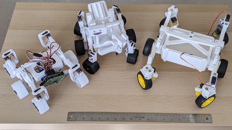
One of the things I knew I wanted to do for my Micro Sawppy rover’s ESP32 brain was an option for wired analog joystick input. This proved useful for Sawppy V1 and I wanted it for Micro Sawppy as well. Not just as a backup control method, but as the first test in my hypothesis that I will benefit from following ROS precedents for generic messages. In addition to the evergreen ambition to give Sawppy autonomy, I want to support the following manual input control mechanisms:

  • Wired analog joystick for noisy wireless signal environments.
  • Web-based control similar to what I created for SGVHAK rover and adapted to Sawppy.
  • Bluetooth based control to connect with devices like the BBC micro:bit.
  • ROS2 joystick control message via micro-ROS.

If I have a generic message type resembling ROS joystick message, each of these input methods can theoretically be isolated in their own FreeRTOS tasks. They all post the same message type to the same message queue, so the rest of Micro Sawppy doesn’t have to care about where their input came from. Swapping input was something very difficult to do on SGVHAK rover software and I want to do improve this time around.

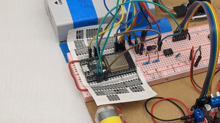
So as a starting point I wanted to take my quick hack of ADC joystick support in my FreeRTOS play project and rewrite it to be something suitably robust for Micro Sawppy. Since it was a quick hack, there were a few weird things that happened but I chose not to worry about it at the time. Thinking I’ll sit down and figure it out later. It is later and… I failed to figure it out. But I did devise a workaround so I can continue with the project. I’ll come back and update this paragraph if I figure it out later.

The issue center around ESP32’s ADC (analog-to-digital converter) peripheral. I had been familiar with ADC peripheral on a Arduino’s ATmega328, which can read values in a range from 0V to +5V via analogRead(). The ADC on a PIC16F18345 works in a similar manner. The ESP32 is a 3.3V chip so I had expected its ADC to read the range from 0V to +3.3V but I was wrong. By default it only reads from 0V to 0.8V. We can configure a signal attenuator to increase range of ADC sensitivity, but even at maximum attenuation it only claims to read from 0V to 2.6V.

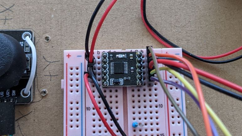
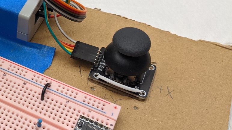
This presents an issue with analog joystick inputs, which are electrically potentiometers that feed a voltage value somewhere between its input max voltage and ground. Wiring such a device up to the ESP32’s 3.3V supply means we’ll lose the ability to read the high end of the joystick corresponding to the range between ADC maximum of 2.6V and 3.3V. It also means the joystick’s center position will return about 1.65V which is higher than midway between 0V and 2.6V. So I had expected ADC readings to be higher than what I would expect.

The reality was just the opposite, they were lower instead. I configured the ADC for 9-bits resolution, so the values are anywhere from 0 to 511. Midway would be 256, but joystick center actually correlated to ~220. And even though I expect to hit maximum value partway through the high range of joystick motion, I never got there. Maximum value never exceeded ~460. I used a voltmeter to measure the input and confirmed +3.3V, but the reading wasn’t close to the actual maximum value of 511. Several rounds of fiddling with configuration flags did not change this result.

So as a workaround, my new joystick code does a range check upon powerup. It assumes the joystick is centered at powerup (hopefully reasonable assumption when they are spring loaded) and waits for me to move each axis through its minimum and maximum values and press the button. Before that first button press, my code tracks the highest and lowest values seen, which are used to normalize joystick message output to the range from -1 to +1 that is used in ROS joystick message. I’m using some very inexpensive joysticks whose potentiometers drift significantly, so maybe a range check is a good idea anyway. Either way it’s good enough for me to move on.

Goals and Challenges for Sawppy ESP32 Software

With a cardboard rover test platform ready to go, I’ve run out of excuses to put off the software portion of micro Sawppy rover work. If my little rover is going to come alive, the software work must be done. This task shouldn’t be as intimidating as it feels, because this is my second round through writing rover brain code. I have learned some lessons from writing SGVHAK rover code running on a Raspberry Pi (code which I then adapted to Sawppy) and those lessons should help me this time on the ESP32.

One goal for my new ESP32 project is to be more ROS-friendly. I’m not ready to dive straight into micro-ROS right now. But when I (or someone else) tackles the challenge, the project shouldn’t be tripped up by something that needlessly complicates the task. I wrote SGVHAK rover code before I knew much about ROS, and in hindsight I made some decisions that made a ROS port annoying for no good reason. For example, the ROS convention for robot forward is along the +X axis. Ignorant of this when I wrote SGVHAK rover software, I chose forward to be +Y axis. The ROS convention for angular measurements are radians for units, and the right-hand rule for positive rotation. Meaning a positive rover steering rotation is counter-clockwise. For SGVHAK rover, I worked with angles in degrees and positive rotation was clockwise. There was no reason to go against these ROS conventions, it was done purely out of ignorance. If I were to adapt my SGVHAK rover code to ROS, a whole bunch of conversions need to occur risking additional surface area for bugs. I completely understand why Rhys Mainwaring wrote a rover ROS software stack from scratch instead, I would have done the same!

So for my upcoming ESP32 Sawppy rover brain project, I’ll keep ROS conventions in mind. Specifically REP103 for units and coordinate conventions. Another ROS-inspired similarity will be messages, which is a new luxury gained by the change in platform. For SGVHAK rover I avoided the complications of introducing multiprocessing concepts to Python code running on a Raspberry Pi. But now I’m targeting the customized FreeRTOS Espressif created to run an ESP32, I gain a lot of multiprocessing tools as a natural and fundamental part of the platform. I will be organizing my code components into FreeRTOS tasks, which has similarities to how ROS organizes code components into nodes. So when my tasks communicate with each other, I’ll look to see if there is a ROS equivalent. I won’t be able to make my FreeRTOS messages compatible with ROS message formats, though. Because I won’t have some of the luxuries like dynamically sized arrays. But the data organization should at least look similar.

I foresee the following items, and I’ll probably find more as I go:

  • I will rewrite my ESP32 ADC joystick code to communicate with a new data message. It should resemble sensor_msgs/Joy from ROS, normalized to the same value ranges.
  • When I write the task which translates raw input into desired rover chassis command, that result will be communicated with something that resembles geometry_msgs/Twist used for ROS topic cmd_vel (Commanded Velocity).
  • When that cmd_vel command is broken down to commands for individual motors and actuators, those individual commands should resemble joint commands of ros_control. I have not yet worked with ros_control myself so this one is the fuzziest with the most unknowns. But I look forward to learning!

And as expected of a learning project, I ran into problems immediately with the first item on the list. I eventually decided to devise a workaround for ESP32 ADC behavior I don’t understand yet.

Test Driving DRV8833 With ESP32 MCPWM

It was time well spent to study my batch of commodity breakout boards for the DRV8833 DC motor driver IC. It reinforced that I should not take random instructions downloaded online at face value, even though in this case the errors wouldn’t have been relevant to my planned usage. Armed with confidence I understand how to use the board I have on hand, I proceed to the next step: verify I could write code to control one with an ESP32 and its MCPWM peripheral.

My self-education FreeRTOS project was created with this future in mind when I started by controlling a L298 DC motor driver IC. The first exercise used the control scheme utilizing three pins per motor (two digital for state, one PWM pin for magnitude) which is compatible with the TB6612 but not DRV8833. The beauty of FreeRTOS was that I was able to isolate code specific to this control scheme in its own FreeRTOS task. In theory, all I would need to do is to write another task with DRV8833’s control scheme (a pair of PWM pins per motor) and swap out the motor driver control task. The remainder of my test program, from the joystick ADC to the heartbeat status LED, would remain untouched and blissfully unaware I’ve switched my motor control task.

I’m happy to report theory matched practice this time! The problem I encountered was unrelated to FreeRTOS. It was really easy to get one motor up and running but I was tripped up by my misinterpretation of Espressif documentation when trying to run two motors simultaneously at different speeds. Each MCPWM unit on a ESP32 can control three motors, and each MCPWM unit had three timers. The quote from Espressif documentation that I misunderstood was:

Each A/B pair may be clocked by any one of the three timers Timer 0, 1 and 2. The same timer may be used to clock more than one pair of PWM outputs.

I tried to run two pairs of PWM outputs (one pair per motor) with the same timer, which is explicitly allowed by the documentation and generated no compiler or runtime errors. However, the fact that it is possible and allowed doesn’t mean it actually does what I want. By using the same timer, I had also locked those motors to the same speed. Different speeds require separate timers. Which is why MCPWM offers up to three timers so we can run each motor at a different speed. Once I realized my mistake and understood what was going on, it was an easy fix to get both motors up and running each with their own timer. With both motors running on my existing cardboard testbed, I thought it was time to upgrade to a fancier (but still cardboard) testbed.


This coding practice project is publicly available on GitHub.

ESP32 FreeRTOS Practice Project Controls L298

After deciding I should learn to use FreeRTOS as part of my ESP32 projects toolbox, I read through the free e-Book PDF. I don’t understand all of it yet, but it built a foundation. Enough for me to start a practice project using some basic FreeRTOS features. What’s the first thing I did? What we always do in embedded hardware: blink a LED!

I’ve used this particular ESP32, mounted on this pink breadboard, for several projects. I had a few external LEDs configured on this pink breadboard for experimentation, and that was because I somehow never noticed that there was a second LED available for direct use on my ESP32 dev module. I knew there was a red one to indicate power, but I didn’t notice the blue one until this project. Apparently this particular ESP32 development board (*) is not a direct clone of Espressif’s official ESP32 DevKitC, because that had only one red LED to indicate power. I have no idea how popular this particular two-LED layout is among ESP32 development boards, I’ll have to keep an eye out as I buy more.

Anyway, this board has a blue LED wired to GPIO2, who still got routed to the same pin as the Espressif module. The LED is wired in parallel and should not interfere with using that pin as output. Though it might affect the signal if I use it as input. I spun up a FreeRTOS task purely for the task of blinking the LED at regular intervals, just to verify I could. My first effort put the ESP32 in an infinite reset loop, and I eventually figured out it was caused by insufficient memory allocated to task stack. I was very surprised that a simple LED blinker needed more than one kilobyte of stack, but it’s not the most important thing right now so I’ll look into it later.

After I successfully created a FreeRTOS task and see it running blinking the onboard blue LED, I proceeded to set up my first message queue. Queues are the simplest way for FreeRTOS tasks to pass data to each other. I copied code from my earlier ADC experiment to read position of an analog joystick, and queued the joystick position message for retrieval by another task. First run of the reader task simply dequeued the joystick position and printed to serial terminal, but that was enough to verify I had the queue running correctly.

With those basic pieces established, I then wrote two more tasks. One reads the joystick position and puts motor control commands into yet another queue, and finally a task that reads motor control commands and adjusts MCPWM control signal for the L298N motor driver accordingly.

This exercise was a good test run to verify I could get the advantages I hoped to get by adopting FreeRTOS.

  • By writing individual subareas as tasks, I could test them individually. In this case, I could smoke test the ADC task by writing another task to read the data it queued.
  • Each task could be in charge of its own ESP32 configuration. ADC configuration is handled by the joystick reading task, separate from the other tasks. And likewise MCPWM configuration is handled by the L298N output task.
  • Tasks are run independently from each other, and more importantly, can be modified independently. I found the blue LED was obnoxiously bright and went into my LED blinking task to reduce the on time to a brief flash and extend the time between flashes, and doing so did not affect timing of other tasks. Reading the joystick and sending motor control signals do not necessarily have to run in sync, I could update motor speed more often than reading the joystick, which would be useful if I wanted to add motor acceleration logic.

That last item is especially important. If I learn enough to design my interfaces (FreeRTOS queues) right, I could swap out FreeRTOS tasks without worrying that I would interfere with other tasks. I want this design to scale from micro Sawppy to regular size Sawppy V2 by swapping out different modules written for different motor controllers. By similar token, it should be easier to do quick hacks like swap out a single steering motor as SGVHAK rover had to do. I also want different control input options, from simple wired joystick to web UI to ROS messages, each of which would be a different task module but they could all use the same message queue format to communicate with the rest of the rover.

Knowing how to set up FreeRTOS tasks and queues aren’t nearly the whole picture of using FreeRTOS, but it gave me a good introduction and built confidence for continuing forward. And as a side effect of this software project, I also made a valuable non-software discovery: cardboard backing for electronics prototypes.

[Source code for this project is publicly available on GitHub]


(*) Disclosure: As an Amazon Associate I earn from qualifying purchases.

Juggling ESP32 Tasks With FreeRTOS

The reason I was motivated to set up better ESP32 debugging support is that I expect my projects to become more complex in the near future. Sawppy V1 had two software control options: a very simple hard-wired joystick control option running on an Arduino Nano, and a more complex wireless system using a Raspberry Pi to serve web pages that display rover driving controls. I had many debugging resources at my disposal working on a Raspberry Pi, but for the Arduino I was reduced to diagnostic text sent over serial and working through the math on paper. That was primitive and I’d rather not be limited to pen & paper when debugging my inevitable ESP32 problems.

One of the tools available in the toolbox of an aspiring ESP32 programmer like myself is FreeRTOS. RTOS here stands for real-time operating system, though it’s far smaller and simpler than what we usually think of as an “operating system” nowadays. And the “real-time” guarantees would meet some needs but not others. I understand FreeRTOS is part of ESP32 runtime by default, used by ESP-IDF to implement some of the APIs exposed to us. On an Arduino the software is completely under our control, and we are directly talking to hardware peripherals in the ATmega328. In contrast running on an ESP32 is a mix, some of the peripheral APIs are implemented in software components before handing off to the underlying hardware.

FreeRTOS allows software projects divide up all the work in a particular product into individual FreeRTOS tasks. Then FreeRTOS will handle cycling through what needs to be done while respecting their relative priorities. This is not absolutely required to implement complex functionality. Teensy’s software framework, for example, was written and optimized to run without a similar RTOS layer. It’s just another tool and Espressif decided it was the right tool for this job.

ESP-IDF makes use of FreeRTOS features and made it available to ESP32 developers as well. There’s a section of Espressif documentation talking about FreeRTOS, including how it is configured to run on an ESP32 as well as the modifications Espressif have made to the base implementation. But the majority of FreeRTOS runs on ESP32 unmodified and I can learn from the source. There’s a free eBook (PDF) that walks through major FreeRTOS feature areas. It is several versions out of date and thus does not cover new features, but it enough to get me get up and running on fundamental concepts.

Once I had a passing familiarity with basic functionality of FreeRTOS, I am better informed as I comb through ESP32 documentation. Things I had previously thought were duplicate functionality (example: FreeRTOS Event Groups versus ESP-IDF Event Library) now made more sense as I understand how they are tools for solving different problems.

Certain projects aim to stay within core FreeRTOS to make things portable across different processor architectures, I believe micro-ROS is one of these projects. At the moment architectural portability is not a concern, especially since I’m focused on the ESP32-specific MCPWM peripheral, giving me freedom to use both generic FreeRTOS and platform-specific ESP-IDF functionality. I might want to separate them out to different architectural layers later, but right now it’s all one big mixing bowl for my first ESP32 motor control project.

PlatformIO JTAG Debug Adventure on ESP32

After I established that I can create a simple project for ESP32 using PlatformIO’s modified version of ESP-IDF, I wanted to see if I can get PlatformIO’s source code level debugging up and running. This is a luxury I lacked in my previous microcontroller development adventures. For Arduino and a few other bits of hardware, my only debugging tool was printing diagnostic text to serial terminal. For other hardware like PIC16F18345, I didn’t even have that much. In theory my PICkit 3 had some limited debugging support but I never managed to get MPLAB X debugging running.

So the promise of debugging support on the ESP32 was pretty enticing. The debugger communication protocol is built on an industry standard called JTAG, and I need to have an adapter supported by OpenOCD to talk JTAG on behalf of PlatformIO. There are quite a few options, but looking over the list I realized I already had one of them: JTAG was also used to debug the Hackaday Supercon 2019 FPGA badge, and as a member of the pre-conference development team, I had bought a Segger J-Link. Since I was not doing any commercial work, I qualified for the licensing terms for the EDU edition. (Item #1369 from Adafruit.) So I went back to my box of Superconference stuff and dug out the J-Link I had bought.

The hardware connections were fairly straightforward, using some jumper wires to connect my J-Link to my ESP32 plugged in to a breadboard. Espressif has documentation on setting up JTAG debugging for an ESP32, and PlatformIO has their own page on the topic. I was sad to see that JTAG debugging would consume several of the already-precious pins that could otherwise be used for GPIO. Cross-referencing with the GPIO pin chart compiled by Random Nerd Tutorials, we see the price we have to pay for debugger support are three “OK with caveat” pins and one unencumbered “OK” pin.

The software connection side proved to be more challenging than the hardware. I didn’t expect it to work right off the bat but I didn’t expect to run into this many problems, either. My first obstacle was an error message LIBUSB_ERROR_NOT_SUPPORTED. A little web searching found that this is the message if there are no drivers installed for the JTAG adapter. I went to Segger’s web site to download and install their software suite, but that made no difference. Further web searching found that it actually wanted the more generic WinUSB driver, which I could install using the Zadig utility. Once installed, OpenOCD could communicate to J-Link, but J-Link could not talk to ESP32.

More reading of various forum posts followed, where I learned a common diagnostics step is to try connecting at a lower speed. This mitigates problems caused by poor connections, which is highly likely in my case as I’m connected using jumper wires and breadboards. I would not be a surprised if it couldn’t sustain the 20MHz connection speed. Looking in the debug output, I see the applicable configuration file is boards/esp-wroom-32.cfg and I found the adapter_khz parameter to reduce the default speed down to 5MHz. But when I ran that configuration, I saw the output was set to 5MHz (yay!) and immediately overridden to 20MHz again (Boo!)

Open On-Chip Debugger  v0.10.0-esp32-20201202 (2020-12-02-17:38)
Licensed under GNU GPL v2
For bug reports, read
	http://openocd.org/doc/doxygen/bugs.html
WARNING: boards/esp-wroom-32.cfg is deprecated, and may be removed in a future release.
2
Info : FreeRTOS creation
adapter speed: 5000 kHz

adapter speed: 20000 kHz

Info : tcl server disabled
Info : telnet server disabled
Info : J-Link V10 compiled Jan  4 2021 16:15:44
Info : Hardware version: 10.10
Info : VTarget = 3.241 V
2
Info : Reduced speed from 20000 kHz to 15000 kHz (maximum).
Info : clock speed 20000 kHz
Info : JTAG tap: esp32.cpu0 tap/device found: 0x120034e5 (mfg: 0x272 (Tensilica), part: 0x2003, ver: 0x1)
Info : JTAG tap: esp32.cpu1 tap/device found: 0x120034e5 (mfg: 0x272 (Tensilica), part: 0x2003, ver: 0x1)
Info : accepting 'gdb' connection from pipe
Warn : No symbols for FreeRTOS!
Error: Target not examined yet
Error executing event gdb-attach on target esp32.cpu0:

Error: Target not halted
Error: auto_probe failed

Examining all the debugger configuration files I could find applicable to ESP32, I eventually found the culprit in the PlatformIO configuration file platform.py for espressif32 platform. It would override speed to 20MHz no matter what the specified adapter_khz value is. Editing that file directly on my computer, reducing to 5 MHz, allowed PlatformIO debugger to connect to my ESP32 running my code. I could set breakpoints! I could see variable values! I could walk the call stack! I could step through source code! This is amazing. I went back to PlatformIO to file a bug, but found that someone had already filed issue #459 and a fix is on its way.

One thing this debugger doesn’t seem to do is to catch fatal issues. I had hoped it would automatically break into debugger if one is attached, but the chip just resets. I was mildly disappointed but I’m happy with what I already have. Besides, it looks like a fatal crash stack decoder is on its way as well. At the moment I’m content because this is far better than debugging from serial port. Or worse, doing it blind. I’m going to need good debugging tools as I start increasing project complexity.

ESP32 Exercise: Stepper Motor Pulses With LEDC PWM

After successfully installing PlatformIO’s ESP-IDF support (and a sigh of relief nothing else seems broken on my computer) I resumed practicing writing code for ESP32. The next exercise was motivated by Emily’s optical audio decoder project where we traded a few e-mail about generating stepper motor signals. For her project she used an Arduino and the AccelStepper library, but it has a maximum speed of roughly four thousand steps per second on classic Arduinos. I was confident the ESP32 can do far better than that, and decided to try it myself.

It was also an opportunity to play with a Trinamic TMC2208 breakout board sometimes called the SilentStepStick. I think this board might be a Trinamic original design, but there’s a slight chance they just hosted materials on their website since it was such a popular use of their chip. Either way, there are a lot of Amazon vendors selling these in affordable multi-packs(*) targeting the 3D printer market. Mostly for people who are unhappy with the high-pitched whine of many inexpensive 3D printers, because TMC2208 is a good choice for helping a printer run much silently than they would on the very popular A4988 driver chip that helped start the current wave consumer 3D printers. My own 3D printers had A4988 drivers soldered on the board so I couldn’t use these modules to upgrade, but I foresee these modules becoming useful in other projects.

In the current Sawppy rover context, these drivers may become useful if I investigate using stepper motors in a future rover iteration. I’ve already received requests to drive and steer Sawppy wheels with NEMA17 style stepper motors commonly used in 3D printers, and there’s always that mythical robot arm that my rover is still patiently waiting for. Commodity NEMA17 motors typically have far less torque than LX-16A serial bus servos, but I’m not sure it is a critical difference for a rover and the best way to find out would be to build one.

But for now I’m just looking at the stepper motor driver, which is commanded by two signal pins: one signifying direction, and another that signals a step for the stepper motor. Direction pin is fairly trivial, it’s the step pin that presents a challenge. Generic portable code like AccelStepper couldn’t reliable pulse the step pin at high speeds, that requires coding to the hardware as GRBL did for the ATmega328.

For the ESP32, my experiment used the ADC peripheral to read the position of a potentiometer and the LED control hardware PWM module to generate step pulses. This module is optimized for dynamic adjustment of pulse width duty cycle during application execution, but stepper motor control is a bit of a off-label use where I left the duty cycle at 50% and changed the PWM frequency at runtime in response to knob position.

According to LEDC peripheral documentation, it is theoretically capable of up to 40MHz pulses at 50% duty cycle. However, for any given configuration, the ESP32 is constrained to a subset of the total range of speed possible. I’m not sure how feasible it is to reconfigure the LEDC peripheral at runtime, but such tricks will be required for anyone with ambition to generate a wider range of pulse frequencies. In my exercise it is limited to a range of 32 Hz to 32.5kHz, which is plenty for today as proof we can surpass the 4kHz limit of AccelStepper on a ATmega328. A stepper motor’s torque diminishes as the speed rises, so I expect the stepper motors will run into mechanical problems well before becoming limited by ESP32 PWM frequency range up to 40MHz.

Once I got this exercise up and running, I started eyeing a desirable luxury advertised by PlatformIO: source-level JTAG debugging.

Code and schematic for this practice exercise is publicly available on GitHub.


(*) Disclosure: As an Amazon Associate I earn from qualifying purchases.

Using PlatformIO For ESP-IDF Development

Based on my limited experience, the installation script for ESP-IDF (Espressif IoT Development Framework) made some assumptions about an ESP-IDF developer’s computer, including the all-too-common assumption that nothing else will be on the computer. This is problematic for several reasons, but the one that made me pull back was Python. Python is infamous for its problems keeping track of different version and their associated code libraries. It’s such a common problem there are tools made specifically to help developers keep Python ancillaries organized. I’ve had first experience with venv and conda and I understand there are many others. In the absence of such isolation in the default installation script, I went online looking for others who have taken a stab at keeping ESP-IDF from messing up the rest of my computer.

I found a few blog posts and GitHub repos, but what made me happy was a reminder that I already have experience with one solution to this problem: PlatformIO has support for ESP-IDF development. I encountered PlatformIO earlier in the context of HX711 strain gauges interface with an Arduino Nano, so my computer already had PlatformIO on board configured for Arduino on classic ATmega328. I can switch it to Arduino on ESP32, but right now I’m more interested in PlatformIO’s promise to make ESP-IDF easy to install, isolate, and eventually uninstall.

There are a few downsides to this approach. First is the fact I’m no longer using ESP-IDF directly, and thereby adding the possibility that a problem might be caused by PlatformIO instead of Espressif or myself. I would also have to switch over to PlatformIO project structure which is not the same as the ESP-IDF application template. This had greater repercussion than I initially thought, because it’s not just a matter of where the source files were placed. While those source files are still calling the ESP-IDF API I can read in Espressif documentation, the portions of documentation about project configuration may or may not apply. When working directly in ESP-IDF, a lot of project configuration is done by running idf.py menuconfig and that’s not necessarily the case anymore. The people who work on PlatformIO ESP32 support recently added some sort of compatibility in response to user requests, so that’s something I’ll have to look into later.

I’m willing to accept some limitations in exchange for PlatformIO’s ability to keep ESP-IDF Python separate from anybody else’s Python on my computer. As long as I can figure out how to do what I want to do on an ESP32… which means it’s time for more ESP32 programming exercises!

ESP-IDF Up And Running on Ubuntu

Since I decided to learn to write code for ESP32 using Espressif’s own tool ESP-IDF for the sake of following official instructions, I went straight to the official directions for installing ESP-IDF and saw it was the “run this one script to install everything” type of instruction. This is not itself a problem, but when I saw that ESP-IDF had a lot of Python scripts, that made me suck air through my teeth. Automated scripts doing unknown things to Python (without mentioning any kind of environment isolation like venv or conda) sets off many alarms. Hesitant to run ESP-IDF installation script on my main computer, I tentatively dipped in my toes by using a computer running Ubuntu I could dedicate to this experiment. A long but uneventful installation process enabled me to compile the ESP-IDF project template and I proceeded to do a few introductory projects on this test machine.

After the trivial blinking light exercise, I moved on to the ADC (analog-to-digital converter) peripheral. When I built a wired handheld controller for Sawppy V1 with an Arduino Nano, its joystick position was read using an ADC and I expect I’ll need something similar again for micro Sawppy running on ESP32. The unexpected twist I had to learn was the attenuation parameter for ESP32 ADC input. Most microcontrollers ADC can read the range from zero volts to input voltage level. (For an Arduino Nano, 0V to 5V.) So I expected the ESP32 to read from 0V to 3.3V. But by default it only reads up to a much lower level and, even with maximum configurable attenuation, it only reads from 0V to roughly 2.6V. Meaning the joystick potentiometer’s center point will not map to the middle of the allowable range of values. But I was able to take Espressif’s sample ADC project and simplifying it for my needs. I removed all the parts that dealt with calibration and conversion to an accurate voltage reading. Such efforts are largely wasted on a low-quality joystick anyway, they drift far more than the ESP32 will.

The next exercise was to take that ADC data and do something with it. I expect to use ESP32 MCPWM peripheral to control micro Sawppy’s six rolling wheels, so I started learning how to use the LEDC peripheral to generate control signals for micro Sawppy’s four corner steering servos. When an Arduino ESP32 project implements the servo() command, they usually turn to LEDC and I decided to follow suit. Generating a one-to-two millisecond signal every twenty milliseconds is well within the capabilities of the LEDC peripheral, and at the end I had a simple ESP32 servo tester generating servo control signals based on the position of a potentiometer.

So far so good. Out of all operating systems at my disposal, Ubuntu was the least problematic one and I’m glad it passed the first few tests. But this was a test computer, with nothing else on it to break. Certainly no other critical Python dependencies. In contrast, Apple Mac OS X is infamously temperamental about its integrated Python and woe to anyone who messes with it.

Windows lies somewhere in between, with no hard system dependencies to fatally break, but still a complicated relationship with Python. Still wary, I whipped up a Windows test computer and ran the ESP-IDF installer. According to ESP-IDF Windows setup page, it was supposed to install associated dependencies including Python 3.7. But when I launched idf.py I got a Python 2.7 error.

error while loading shared libraries: libpython2.7.so.1.0: cannot open shared object file: No such file or directory

Ugh, what a mess. Now I’m very glad I had used test computers for these experiments. I shall proceed to wipe them clean and consider alternate options.

[Practice projects described in this post are publicly available on GitHub]

Evaluating My Options for ESP32 Development

Once I decided I could use ESP32 as a micro Sawppy rover brain, the next decision is how I intend to write my code to run on an ESP32. Since it’s such a popular microcontroller, I have many options that I’ve narrowed down to top three candidates: ESP-IDF, Arduino, and MicroPython.

The lowest level option is ESP-IDF: Espressif IoT Development Framework. This is the software development kit released by the same people who made the ESP32 hardware. All sample code in Espressif documentation will be targeted to ESP-IDF, so this is the best option if I’m working from the official reference sources. This is important when working with less-popular features like the MCPWM module designed for motor control: I can be confident the feature will be supported.

The mid-level option is Arduino adapted for the ESP32 hardware. Setting up the Arduino IDE for ESP32 development is a very simple process compared to the setup procedures for ESP-IDF. It also allows access to the huge catalog of Arduino libraries that exist out there. Or at least the subset that don’t have hardware dependencies. Code that is hard-coded for ATmega328P won’t run on an ESP32, but that problem is shared with other non-AVR Arduino compatibles like Teensy or even the newer Arduino boards. Architecturally this is a translation layer on top of ESP-IDF, so non-ATmega328P features like MCPWM can be accessible as long as the proper header declarations are in place. Which, in the case of MCPWM, they appear to be.

The high-level option is MicroPython for ESP32. Where the user doesn’t even really need to install anything on their computer: anything that can open a serial terminal will do. The Python language itself is much more beginner friendly than the C language used by Arduino and ESP-IDF. However, a search for MCPWM support found that it is currently a work-in-progress, eliminating it from consideration for this project.

With that elimination my choices are between using ESP-IDF directly versus the Arduino translation layer, I favor direct usage because I saw it as eliminating a variable. When my code doesn’t work, I won’t have to wonder if it’s a bug in my code or in ESP32 Arduino core. While not a huge concern in the well-trodden paths, it is a worry when I venture to less popular sections like MCPWM. And since I’m using an ESP32-specific peripheral, this code won’t run on any other Arduino-compatible boards anyway. Might as well go straight to the source.

Micro Rover ESP32 Brain Is Feasible

I was a little disappointed when I learned that the ESP32 can only use a tiny fraction of its vast peripheral interface capabilities due to the fact there are only a few physical I/O pins to be allocated among them. But to be honest, roughly 20 is a fair number in terms of controllers in this price range. It’s only “few” when compared to literally hundreds of possible uses for those pins. It also makes sense when we think about the target market for the ESP32: it was derived from the ESP8266, and they are both intended to act as a WiFi interface to some device, not to be in charge of a large complex thing. So does my little rover qualify as a small focused-purpose device that needs a WiFi interface? I think so, but it’s a tight fit.

I originally intended to drive L298N by digitally setting the direction on its two input pins and put a PWM signal on the enable pin to control velocity. The straightforward implementation of this would require 3 pins per wheel. Six wheels mean 18 pins, and I still need four more. One for each of the four corner steering servos. I don’t think I can get 22 output pins on the ESP32 dev board I have. Fortunately it isn’t quite that bad, because all three wheels on one side of the rover are always rotating in the same direction, so they can share the same direction control pins. Two pins to control all left wheels, two more to control all right wheels, and one pin for each of the six wheels for PWM add up to ten pins, plus four more for corner steering servos add up to fourteen pins. This will work.

Alternatively, I can implement the control scheme used by Espressif’s sample program for controlling a L298N motor controller using ESP32 MCPWM peripheral. I’m skeptical of this one, though. It wants the enable pin to be tied high, and controls speed by using PWM signal on the direction pins. As per my understanding of L298 data sheet, this toggles between powered state and brake state. Which sounds like an extremely inefficient way to control velocity. Nevertheless, doing this would require 2 PWM pins for each of the six wheels. Plus the four corner steering pins for sixteen output pins. Even though there are only fifteen easy to use output pins, I can probably make one of the caveat-encumbered pins work for the sixteenth.

The final consideration: what would happen if I decide I don’t want to use the L298, and want to use a different motor controller instead? I haven’t studied them as much as I’ve studied the L298, but the few I’ve glanced at appear to use one of the two above control schemes. Perhaps the L298 is established enough that most newer DC motor controller offer drop-in compatibility with L298 control signals? Even if not, I believe a mini rover using another DC motor controller would still be feasible to implement on an ESP32. And the best way to know for sure is to start writing some code.

Notes on ESP32 Input Output Pins

As I combed through ESP32 documentation for information on its PWM capabilities, I realized there was something missing from what I expected to see: information on which physical pins are associated with these PWM peripherals. This was something I saw and learned to expect from reading documentation for other microcontrollers like the PIC16F18345. When I read about a peripheral, it is always accompanied by a chart showing which physical pins are wired to that peripheral. But not the ESP32.

The reason became obvious as I started browsing ESP32 peripherals, a list that just kept going on and on and on. There are so many features on this chip for doing so many different things, how can we possibly use them all? Well, sadly, we can’t. Only a small fraction of this chip’s internal capabilities can be routed to the limited number of external pins. So this chip can do many interesting things, but it can’t do them all at the same time.

The key documentation here is the ESP32 Technical Reference Manual. (PDF) Section 5 talks about the GPIO matrix, which is what we configure when we write an ESP32 application using GPIO peripherals. According to this document, all the ESP32 peripheral inputs added up to 162 potential signals, and all the outputs added up to 176 output signals. The GPIO matrix is how we control which of those 338 (!!) pins are routed to the 34 physical pins actually available on an ESP32. I found it amazing that, by definition, we could only use ~10% of an ESP32’s input/output capabilities.

And in reality, we are even more constrained than that. Especially when working with a ESP32 DevKit module as I am. The physical appearance of 38 pins are a little misleading, because there are multiple ground pins (all tied together, at least on my board) and both input and output voltage of the onboard 3.3V regulator. Six pins are tied to onboard flash memory and thus not available for use, and given the fact they are unusable I’m puzzled why they even broke them out on the dev kit. The UART for uploading programs are also exposed, meaning a few more pins unavailable for projects. Then there are pins involved in the boot and firmware upload process, and those involved in JTAG debugging.

I found it all very confusing, but thankfully I found an ESP32 GPIO reference chart by Random Nerd Tutorials which I consider a great resource for navigating this particular jungle. According to this chart, there are only 15 GPIO pins that an be used without caveats. Four more are limited to input-only and lack internal pull-up or pull-down resistors. Roughly 4-6 more pins are available depending on my appetite for adventure and confidence, followed by their associated restrictions. The rest might as well have been marked “HERE BE DRAGONS” and I’m staying away from them for my micro Sawppy brain project.

Notes on ESP32 PWM Peripherals

Now that we’ve celebrated the success of Perseverance rover’s arrival on Mars, I resume working on my little rovers. I was happy to discover that I’m less intimidated by the ESP32 than I was over two years ago. I now have a basic understanding of its capabilities and the ecosystem that has grown up around it. Enough to figure out where to start if I have a problem to solve. And the problem of the day is to determine if micro Sawppy can use an ESP32 as its brain.

The reason I started looking at the ESP32 is because of its WiFi capability and its low cost. I liked the idea of web browser-based UI like what I wrote for SGVHAK rover and adapted for Sawppy. But that ran on a Raspberry Pi which, even in its lowest-cost Pi Zero form, is far more expensive than an ESP32. My experience with other ESP32 projects like Ben Hencke’s Pixelblaze and Bart Dring’s Grbl port taught me the ESP32 is quite capable of serving up HTML user interfaces. So the next thing to do is to verify an ESP32 can generate all the control signals for a Sawppy rover, which means investigating its PWM capabilities.

PWM (Pulse Width Modulation) is a tool that can be used to solve many problems in a microcontroller. For micro Sawppy I need PWM capability to control four steering micro servos and the six wheel drive motors. It doesn’t matter if they are micro servos modified for continuous rotation or a real DC motor driver like the L298N, they all need PWM signals. And what I found was that no only can ESP32 generate PWM signals, it has separate interfaces dedicated to specific problem someone might want to solve with PWM.

First up is LEDC, the Light Emitting Diode Control module. I bring this up first because our first project with any new piece of electronics is to blink a LED, and in many tutorials the next step is learning how to vary the brightness of a LED via PWM. LEDC is designed with the intent of controlling intensity of up to 16 LEDs via PWM.

Another problem commonly solved with PWM is to convert a digital signal into an analog one. This is sort of like controlling the brightness level of a LED, but some applications are sensitive to the sharp pulse transitions of a PWM signal. One example is for generating sounds, which needs a smoother output. And here the ESP32 delivers a dedicated DAC (digital-analog converter) peripheral. Anticipating that this would be used for audio, Espressif provisioned it to interface with I2S which is popular with audio applications. This may be fun to look at later, but it is not critical for driving a little rover.

And finally, I was surprised to find there is a dedicated Motor Control PWM module for generating PWM signals sent to motor driver modules like the L298N. It included many motor-specific features absent from LEDC, but they are mostly aimed at controlling brushless motors which usually have three coils each requiring independent control. ESP32’s MCPWM is set up to control two brushless motors, which means controlling six coils. But it is not required to control brushless motors, each of those coil control an be used to control a single DC brushed motor.

So the ESP32 MCPWM peripherals can control six brushed DC motors, which is a perfect fit for a six-wheel-drive little rover. I should be able to use four channels of LEDC to generate PWM to control four steering servos. This first pass over the spec sheet supports the idea of using ESP32 as little rover brain, though there is a potential problem in assigning control signals.

ESP32 Feels Less Disorienting This Time

Seeing all the interesting projects built with an ESP32 has made me interested in learning more about the popular platform, but it wouldn’t be real until I dedicate the time and focus to build some projects of my own. My micro Sawppy project might be the motivation I needed to get down to business.

Querying in this blog’s history, I was embarrassed to realize that it’s been over two years since I first thought I would build something with an ESP32. My first exposure to the fire hose of information online was overwhelming. But I returned occasionally to pick off little bite-sized pieces to digest. Reading documentation on some specific aspect on the ESP32 at a time, usually in response to seeing someone’s project making cool use of that particular aspect. I wanted to see how it was done!

During this incremental learning, I picked up on the fact something is coordinating the works to keep all the plates up in the air. Eventually learning that the default ESP32 runtime environment includes a minimalist operating system for embedded hardware: FreeRTOS. Which was a world onto itself! There is a tutorial e-Book to help get people up to speed but again, it is a lot of information that I had to digest a little bit at a time. I’ll write more about FreeRTOS later.

And though I hadn’t reached the point of writing my own ESP32 code, I did start getting a bit of hands-on experience working with an ESP32 developer board. Which was more full featured than the minimalist mesh networking Supercon hack that was my first introduction to the hardware. Even though I was only running other people’s code (like Bart Dring’s ESP32 Grbl port) and not my own code, it was valuable familiarization of the ESP32 landscape.

All of these individual pieces built up a comfort level that was absent from my first time facing the avalanche of information available for ESP32 over two years ago. Now I can look at the page like ESP32.net and have a much better understanding why things are organized the way they were, and which pieces of information are relevant to others. This knowledge map is important as I do some basic due diligence to see if it’s feasible to build a micro Sawppy brain from an ESP32. Before I get any further on my little rovers, though, there’s a big event for a big rover.

Thoughts on Micro Sawppy Brain

My diversion to learn a bit of Unity 3D was a good change of pace, but now I will set that aside and return to rover work. My latest little rover Micro Sawppy Beta 3 (MSB3) had a few interesting features that I reviewed before taking this Unity break, most recently a few notes on MSB3’s living hinge differential link. MSB3 was built around the TT gearbox, which requires DC motor drivers commanded by some kind of rover brain.

I have the option of using the same brain I used for MSB1 and MSB2, which was adapted from Sawppy V1 and allowed me to control everything with servo PWM control signals. This worked for MSB1 and MSB2 because they were all micro servos. Four in their original form for steering, and six modified to continuous rotation to drive the wheels. But now that I’ve converted rover locomotion to DC gear motors, I’ll have to switch to something else.

My current generation of rover software was originally written for SGVHAK rover, which had DC motors in its wheels and used RoboClaw motor controllers. Those are nice, but far too expensive for my micro Sawppy price target. Or I could continue controlling via PWM by using forward/reverse brushed DC motor controllers(*) from the world of remote control hobbies. These are far less expensive than RoboClaw controllers but also less capable. Unfortunately they are still too expensive to meet my price target. Motivation to find a cheap commodity was why I investigated commodity L298N driver boards earlier.

But I’ve always known I couldn’t keep using a Raspberry Pi. In order to meet my price target, I have to swap it out for something more affordable. For MSB1 I chose to use the Pi as a known quantity, because the rest of the rover was all new and I wanted to reduce the number of unknowns for the first prototype. After several revisions I’m at MSB3 and I’ve decided it’s fine if a baseline micro Sawppy didn’t have the computing power of a Raspberry Pi as long as there are provisions for people to upgrade if they wish. So any microcontroller capable of generating the required PWM control signals (for servos and for L298N motor drivers) would suffice. The classic Arduino is always the first candidate I consider for a project, but ATmega328P based Arduinos only have 6 PWM channels. That’s not enough here so I have to move upscale.

Classic ATmega328P-based Arduino are also missing another very important feature: WiFi. SGVHAK rover’s Raspberry Pi based brain served up a web browser-based rover control interface. Controlling Sawppy from my touchscreen phone was very useful. Not just because of convenience but also because I didn’t need to worry about building a separate device to act as handheld controller. Which, in a bit of cheat, also meant I did not counted the cost of controller phone in micro Sawppy budget. I justified this by saying many people today have old web-capable touchscreen phone or two sitting around collecting dust. Maybe a stretch, but I’m going with it!

If I want something more powerful than a classic ATmega328P-based Arduino, but more affordable than a Raspberry Pi, and can handle web-based network traffic over WiFi, the top candidate is pretty obvious: ESP32, we meet again.


(*) Disclosure: As an Amazon Associate I earn from qualifying purchases.

Micro Sawppy Beta 1 Electronics

The past several posts have described various aspects of Micro Sawppy Beta 1 (MSB1) that are explorations of new ideas for a little rover. Since there were already many new ideas piled onto the little guy, I decided the control electronics and software should step back and reuse known quantities. Even though I don’t intend this to be the final approach, I wanted to reuse existing components here just to keep things from going too wild and confused if the little rover should encounter problems.

Hence the onboard electronics of MSB1 is very close to those used on Sawppy, which was in turn adapted from code written for SGVHAK Rover. Not from the official JPL Open Source Rover instructions, but the hack I hastily slammed together for its world premier at Southern California Linux Expo. Back then we faced the problem of a broken steering gearbox a week ahead of the event, and it would take over a week for replacements to arrive. So while Emily hacked up a way for a full-sized RC servo to handle steering, I hacked up the rover software to add option to control a servo via what I had on hand: the Adafruit PWM/Servo HAT.

Years later, I still have that same HAT on hand and now I have a rover full of micro servos. Putting them together was an obvious thing to try. My software for that servo steering hack turned out to be very easy to adapt for continuous rotation servos powering the wheels. (Only a single bug had to be fixed.)

There was another happy accident: since the SGVHAK rover software already had software provisions for steering trim, it was easy to use that for throttle trim as well. This was useful to compensate for the fact that the converted continuous rotation servos in the six wheels aren’t necessarily centered like they theoretically were. Resistors with identical markings don’t actually offer perfectly equal resistance, and the control circuit of a cheap micro servo isn’t very good about precise voltage measurements anyway. If I didn’t have this software throttle trim control, it might have been much more difficult to get MSB1 up and running.

For power supply I had a small 2-cell Lithium Polymer battery on hand, previously seen on these pages in exploration of a thrift store Neato. Dropping its voltage (8.4V when fully charged) down to something that wouldn’t fry the micro servos was the job of MP1584 buck converters. I had discovered these worked well for powering a Raspberry Pi and one of them is again enlisted into that role. In order to reduce the chances of a power sag causing the Raspberry Pi to reset, I added a second buck converter to give the micro servos an independent power plane. Both buck converters are soldered onto the little prototyping area Adafruit provided on their HAT. Once I had the electronics circuit stack assembled, I could start wiring up all the components.

Goodbye and Good Riddance To This Generation of Hybrid Drives

I have successfully upgraded a HP Pavilion Split X2 (13-r010dx) to use a modern M.2 SATA SSD with the help of an adapter circuit board. The results were stellar and, even though the adapter does not mount inside the computer properly, I have no plans to put the original drive back in. It was a compromised solution of its era and times have moved on.

A little over ten years ago, flash-based solid state drives started edging towards price levels affordable to normal computer buyers. A few bargain basement devices were released, and they were terrible. I had two JMF602-based drives that lasted through their 90-day warranty periods but not much beyond that. The big breakthrough in affordable and durable performance is credited to the Intel X25-M, but the capacity was quite small. SSD performance is something that I had to experience to be converted to a fan, and it was hard to get non-converts to accept living with 80GB of capacity when we had become accustomed to hundreds of gigabytes.

The compromised solution was the SSD/HDD hybrid drive: there is a magnetic platter hard disk drive, but there is also a small piece of flash memory acting as a small solid-state drive cache. The advertising proclaimed that we would get the capacity of a HDD with all the performance of a SSD. I thought the concept was enticing, but never actually got one to try.

I’m glad I did not, if this computer’s stock WD5000M21K hybrid drive is representative of the breed. Its performance was absolutely terrible. Maybe modern workloads overwhelmed its meager 8GB of flash cache. Maybe years of use has worn out the flash and there was no caching anymore. Whatever the reason, its performance was no better than a HDD, definitely nowhere near the performance of a real solid state drive.

Now solid state drives with plenty of elbow room are quite affordable, giving old computers a new lease on life. The hinderance of oddball connectors like the SFF-8784 become just a speed bump with help of adapters, so we don’t need to put up with the compromises of SSD/HDD hybrid drives anymore.

No Good SSD Adapter Mounting Option

Upgrading to a SATA SSD was a hugely successful transformational upgrade for this old HP Pavilion Split X2 (13-r010dx). Physically, it was only a tiny improvement to the problems of heavy weight and it doesn’t nothing to help the low 1366×768 resolution screen, but the computer is now immediately responsive to user input and no longer miserable to use. That is the good news.

The bad news is that Sintech’s SSD adapter didn’t have mounting holes to line up to original mounting brackets. I originally thought I could 3D-print something to adapt its vertical mounting holes to horizonal, a simple rectangular loop should do the trick. Then I took a closer look at the dimensions and realized it’s not so simple.

The circuit board height where the interface plugs into is fixed and that height is in the middle of the screw holes. In order to clear mounting screws I would have to cut into the circuit board, which I’m not prepared to do. I already had to wait for a replacement to be shipped to me once, I didn’t want to ruin a board and have to wait again.

I considered offsetting vertically to clear the screw holes, moving in one direction or the other. But the overall height of this adapter + M.2 socket is barely any thinner than the original hard drive, leaving very little margin to work with. Pushing towards the screen, I could not move far enough to clear the screws. Pushing towards the back, clearing the screws would bump against the back cover.

So no 3D-printed adapter bracket for me. I ended up using double-side tape sold for attaching Raspberry Pi heat sinks, and used that to attach the SSD to the chassis. This solution is not ideal, but I’m not willing to revert to the stock hard drive because it was something better left to the past where it belongs.

HP Split X2 (13-r010dx) Transformed with SSD Upgrade

With a SSD adapter circuit board temporarily held in place with painter’s tape, I powered up this old HP Split X2 (13-r010dx) to see if it’s willing to run on a modern M.2 SSD. The answer is yes — and quite well!

I have a USB flash drive prepared by the Windows Media Creation Tool for installing Windows 10 2004, and I could select it as the boot device by holding down F9 upon power-up. From there it was an uneventful Windows 10 installation, automatically activated by a Windows 8 license embedded in hardware.

Here is the “Before” picture, taken a few minutes after the computer has booted up on the original WD5000M21K hard drive. The computer is completely saturated with Windows startup tasks and it takes a few minutes to even get Task Manager up and running and a screenshot tool. From here we can see we’re doing well on memory, with only half used. The CPU is largely idle. They are all waiting for the disk.

Here is the “After” picture, taken shortly after the computer started up for the first time running Windows 10 freshly installed on the M.2 SSD. Disk overhead has stopped being a constraining factor. The memory is about the same, and now the humble low power Core i3 CPU is the constraining factor as this computer is chewing through information to decide what to download from Windows Update.

Once Windows was up to date, all drivers were automatically installed, and this computer was ready to go. A reboot verified that startup time has gone from several minutes down to less than 30 seconds. Launching and switching between applications are nearly instantaneous. When the meager 4GB RAM starts running low, virtual memory on the SSD is perfectly usable and not the molasses slow torture session it used to be.

The Core i3 might be the low end of the Core line, but it is far faster than an Atom chip of similar vintage. Freed from the shackles of its molasses slow stock HDD, this computer is now perfectly comfortable running up-to-date Windows 10 and modern applications. This SSD upgrade has proven to be a hugely beneficial transformation for this old computer. Which was fantastic! Except for one problem… how do I make sure it doesn’t rattle around inside the machine?

HP Split X2 (13-r010dx) SSD Upgrade: Round 2

I now have a M.2 SATA SSD available for experimentation, mounted on a Sintech ST-NG8784 adapter circuit board that lets me plug a M.2 SSD into a SSF-8784 connector. This unusual slim connector is used by a HP Pavilion Split X2 (13-r010dx) tablet/laptop convertible computer, which foiled an earlier attempt at SSD upgrade. This time I am better prepared.

Here’s the “Before” picture, with the stock SFF-8784 hard drive in the center. From the factory the interior of this device had a lot more tape and foil, including foil completely wrapping the hard drive. They’ve all been pulled off in earlier adventures.

In addition to disconnecting the AC adapter, the connector at the center of the image (with black wires, not white ribbon cable) is for the battery and should be disconnected before working on this machine.

Four screws held the drive in place using some metal brackets, which were in turn mounted to the drive via some screws on the side. Removing them were trivial, but that exposed the next problem: the PCB could match bottom mounting holes, but we need horizontal ones, so there’s no good way to fasten the drive.

I decided not to worry about proper fastening for the moment, because I had no idea if the computer would even accept this drive with adapter. Some temporary painter’s tape is enough to make sure the board doesn’t flop around while I experiment.