Type 623 Ball Bearing For Small Rover

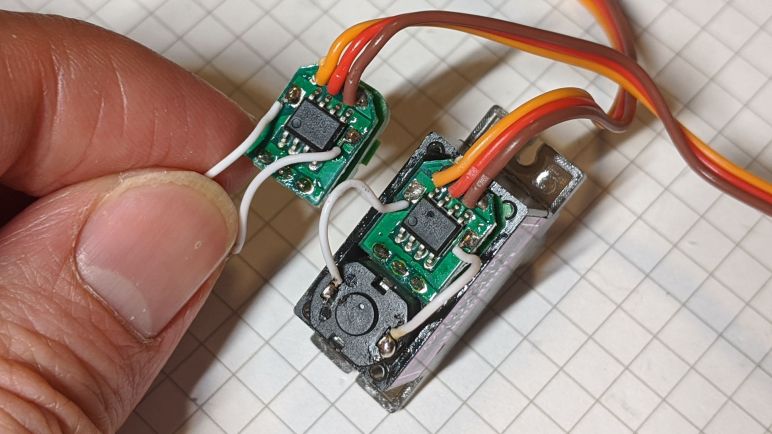
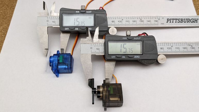
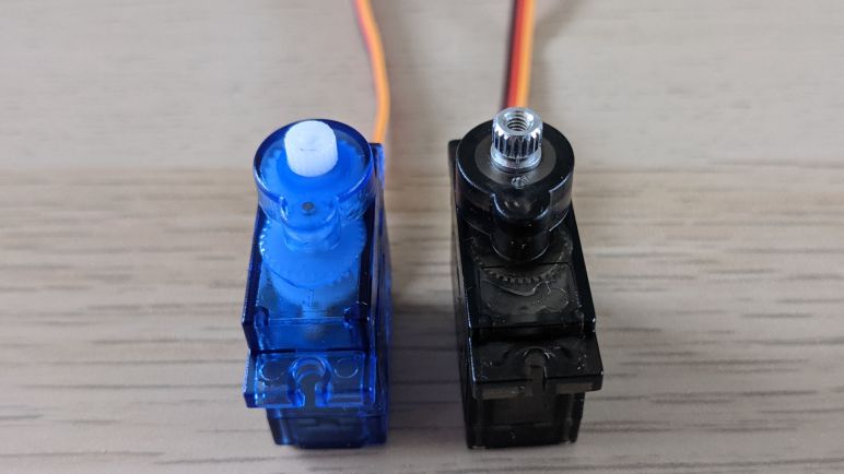
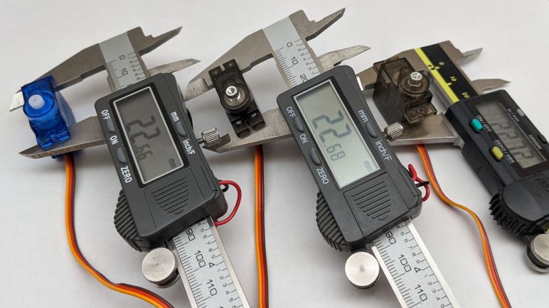
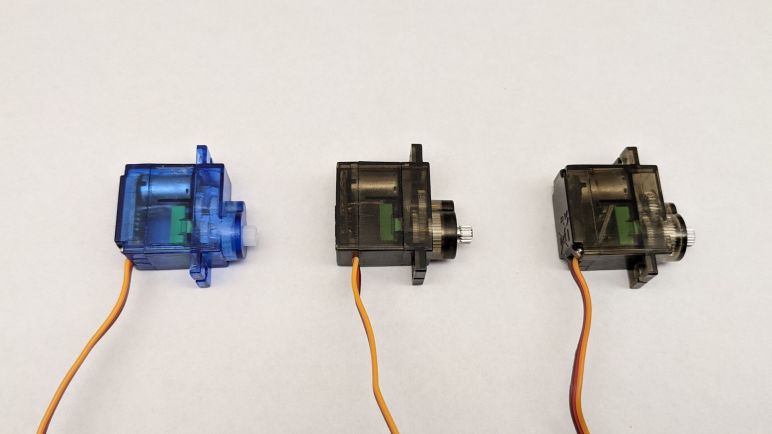
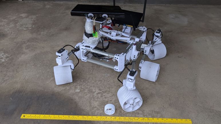
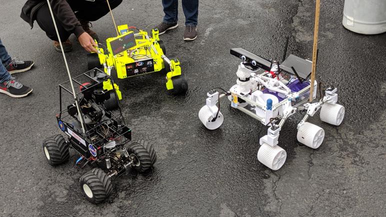
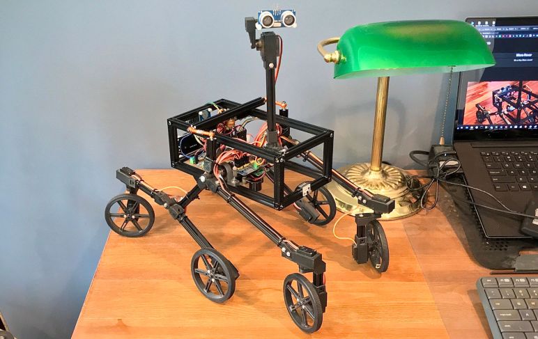
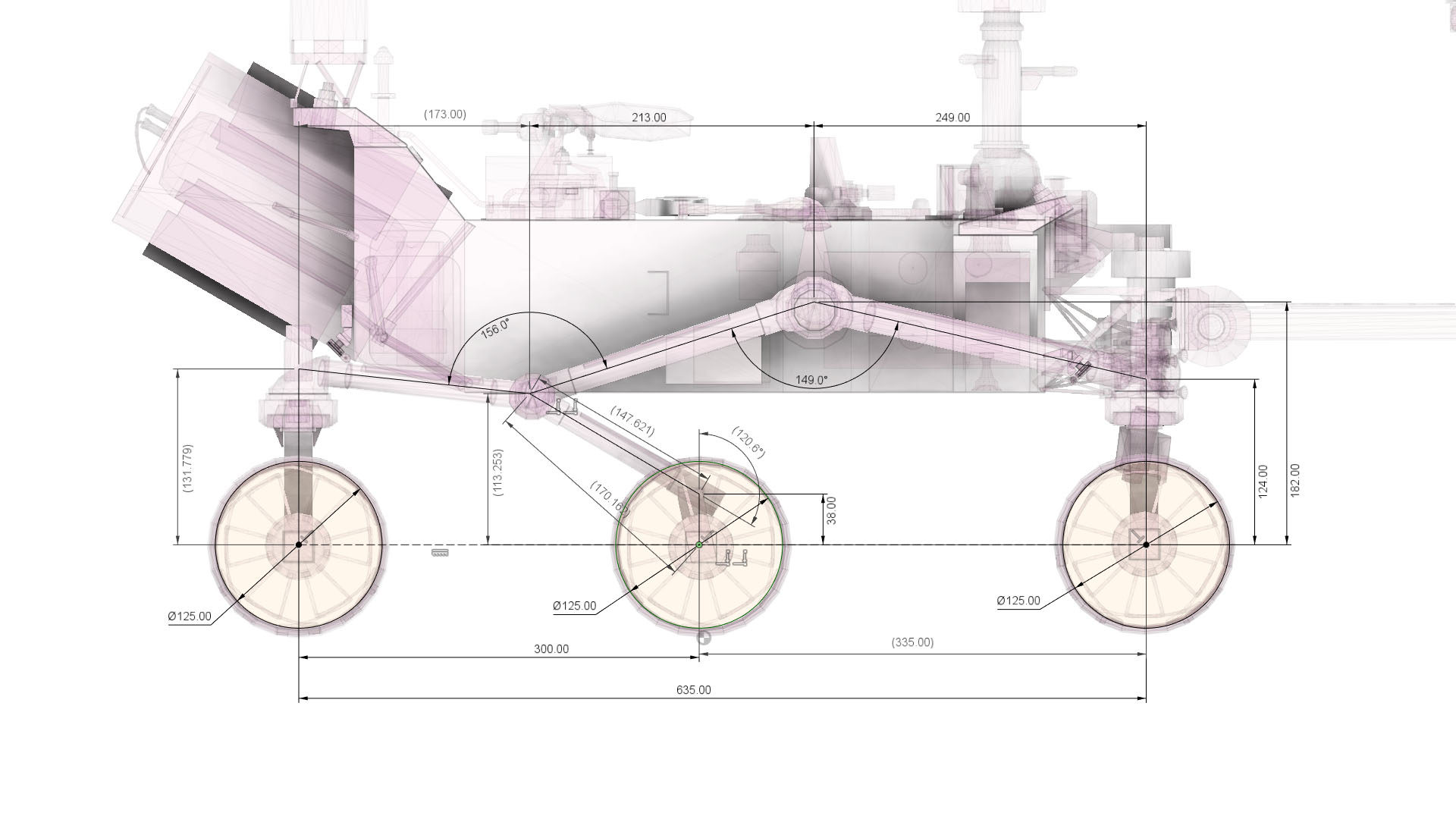
I want to design a smaller and affordable variant of my Sawppy rover. I’ve been looking over the mechanical and electronic properties of micro servos I intend to use as the little rover’s actuators. They represent the biggest mechanical unknown due to the variations between products in this generic category. Thankfully, consistency is much better in the other mechanical part impractical to 3D-print: ball bearings.

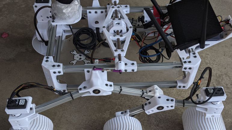
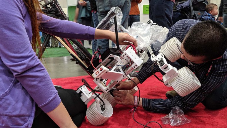
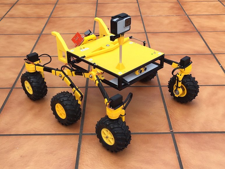
Using ball bearings are apparently “My Thing” when it comes to designing and building rover models. When I reviewed other rover projects earlier, several didn’t use ball bearings at all, and most of the rest only used ball bearings on a subset of rotational axes. I want to put them everywhere I can!

Every rotational axes of Sawppy V1 were supported by ball bearings that went by the designation 608. I first came into contact with this type in the context of rollerblades, and they’re popular in other related wheeled footwear such as roller skates and skateboards. However, 608 bearings would be unnecessarily large for a little rover, so I went back to the well of mass-produced commodity ball bearings to find something suitable for a smaller rover.

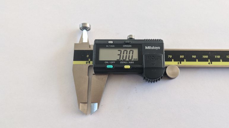
My primary criteria is an inner diameter of 3mm, because I thought M3 would be a good fastener to use for the little rover. It is a metric standard commonly available worldwide. M3 fasteners were also used extensively in Sawppy V1, but they were on the small side so I compensated with sheer numbers. That was a design decision I regretted and want to fix in the future. For the little rover, M3 would be relatively big and strong so I would only need a few of them.

There are several different common bearing types with a 3mm inner diameter, and an unscientific poll of Amazon vendors hinted the 623 bearings (*) are the most popular and least expensive among them. I thought it was interesting that they were still more expensive than the batch of 608 bearings I bought (*), and I take this to mean that significantly more 608 bearings are produced than 623. Either that or I have yet to find the right outlets. A little rover can happily use cheap 623 bearings that have failed rigorous quality assurance tests for industrial use, as those “bad” bearings will still be far superior to nothing at all. But for now I’ll be content with the lowest bidder of the day. (*)

Like 608 bearings, the letters and numbers surround 623 designate various other related features, such as how the ball bearings are shielded from the environment. But 623 itself is the important part here, as it describes an inner diameter of 3mm, outer diameter of 10mm, and thickness of 4mm. And generic 623 bearings will follow these dimensions much more tightly than generic micro servos adhere to their mechanical dimensions. Which is one less thing to worry about when I already have to compensate for varying dimensions of 3D-printed plastic that will host these bearings.


(*) Disclosure: As an Amazon Associate I earn from qualifying purchases.

Notes on Micro Servo Electronics

Examining my batches of micro servos unveiled a lot more mechanical variation than I had initially expected, even before we get into fine details like plastic injecting molding draft angles. But I got enough of an understanding to start pondering how I’d mechanically accommodate designs across the generic spectrum, so I started looking at the electrical side of things. Given the mechanical variations, I now know to expect their electronics to be different, and that was the correct attitude.

Three micro-servos from three different batches, and a casual glance is enough to tell there are three distinctly different control boards. (Plus examples from a fourth batch, in other pictures of this blog post.) Two of them have the motor soldered directly to their PCB, the third example here has a smaller circuit board but then must take the extra cost and assembly processing of motor wires. The three potentiometers are slightly different, but all of the motors are externally identical. Implying a commodity form factor that I am currently ignorant about, but can set aside to investigate later.

In their product listings, all of these micro servos were listed with an operating voltage range from 4.8V to 6.0V. This traces back to the days of hobby remote control receivers, which can operate from 4 Nickel-Cadmium rechargeable battery cells in series. Each cell has a nominal operating voltage of 1.2, so 4 * 1.2 = 4.8V. However, the voltage of a fully charged cell is 1.5V, so servos must be able to tolerate up to 6V.

To explore the low end, I connected a servo tester to these servos and drove them at 4.8V. While all of the SG90 seem to operate well at that voltage, there was a surprising outlier in the MG90S. One batch could work at 4.8V, but just barely. If the voltage drops below 4.8V at all it stops responding. This could happen when the battery cells get low. This could also happen when connected to a servo extension cable, or by the jumper wires I had used.

I found this curious. Does it mean this particular servo design expected higher voltage? For full size servos, it is now fairly common to accept nominal power of 7.4V, which is two lithium chemistry battery cells in series. Perhaps this particular micro servo was designed for lithium batteries? I increased the supply voltage up to 7.4V and it continued to function. But that is nominal voltage — fully charged lithium rechargeable batteries deliver 4.2V per cell or 8.4V for two cells in series.

Supplying this micro servo with 8.4V resulted in an audible pop and a visible flash. This gave me an answer: no, this micro-servo is not designed for lithium rechargeable batteries. Taking a closer look at the control board, I see a hole in the control chip right next to the power supply wire that delivered the killing 8.4V. In this picture a red arrow points to the hole, and I held up another control board from the same batch (without hole) for comparison.

Now that I’ve established 4.8V is too low for reliable operation with certain generic servos, and 8.4V is definitely too high, I’ll aim to supply somewhere in the 5V-6V range. With that electronics baseline established, I switch focus to the bearings I will use for this micro servo Sawppy rover.

Notes on Micro Servo Horn

I had toyed with the idea of 3D-printing parts that would bolt directly onto a micro servo’s output shaft. But after studying the variation in output shaft dimensions from a few different batches, I’ve changed my mind and plan on using the servo horns that come bundled with each servo. These horns will have the best chances of fitting and matching properly.

Even though these servo horns are all plastic, there are differences beyond cosmetic color: they also vary in thickness and strength. Servos sold under the MG90S category usually (but not always) have stronger servo horns than those sold under the SG90 banner. Here I am pushing two servo horns against each other and we can see one deflects much more easily.

The next challenge is the variation between their shapes. All of these micro servos came bundled with three horns, featuring one, two, and four protrusions from their center hub. The smaller protrusions found in the four-point version seem to match, but they wouldn’t have much leverage. I wanted to use the larger protrusions, but here we see variations as well. There appears to be at least two popular profiles, with slightly different shapes, lengths, and number of holes. I don’t know the history here, but I assume there were two popular types at one point and these generic models copy them both. Lacking names I will just refer them as SIX and SEVEN after the number of holes in each profile.

It would be convenient if the holes on SIX lined up with the first six hones on SEVEN, but no such luck. They have slightly different spacing. It also seems popular to have both profiles represented on the four-protrusion variant of the servo horn, making it asymmetric.

This particular SG90 servo has the asymmetric four-protrusion design, SIX on the right and SEVEN on the left. The two-protrusion design is symmetric with SIX on both left and right. For the smallest horn, it decided to go with the SIX profile.

This particular MG90S made similar choices for the two- and four-protrusion horns, but the smallest horn went with the SEVEN profile instead.

This pattern seems to hold with the servos I’ve bought to examine, but I don’t know how far to trust that observation. Are there micro servos out there with SEVEN+SEVEN for their two-protrusion horns? Are there any using symmetric four-protrusion horns? Just because I don’t see them in my batches doesn’t mean they don’t exist. This is all very puzzling to me because I’ve seen designs for 3D printed contraptions that incorporate slots in the shape of these horns. How do they account for these variations?

With all these variables in thickness, strength, shape, length, it’s not obvious how to design a rover that can employ arbitrary generic micro servos. This is a challenge to ponder.

But to end on a bit of happy news, it seems like there’s one final de-facto standard dimension that all these designs adhere to: despite the variation between servo horn thickness and mounting tab thickness, it appears that the distance between the bottom of the mounting tab to the top of the servo horn is fairly consistent. Again there’s no guarantee all the micro servos out there would adhere to this convention, but at least it gives me a starting point on mechanical design as I move on to look at the electronics within.

Notes on Micro Servo Output Shaft

Mounting a micro servo in the chassis is only half the battle, we also need to attach something useful to its output shaft. Historically servo horn is one of those things that aren’t practical for FDM 3D printing due to the precision fine teeth required to engage output shaft splines. I had thought it would be an interesting thing to try if I ever have access to a high resolution resin 3D printer, but after this study session I’ve changed my mind: there’s too much variation between servos and I’ve come to accept that I’ll need to use whatever horn that came bundled with the servo.

Or at least that’s true at this low-cost end of the generic micro-servo market. My previous knowledge came from the market of standard sized servos, where there are two fairly established brands (JR and Futaba) each with their de-facto standards that other servo makers typically emulate. That might be worth investigating for later for a larger rover, but we’ll set that aside and stay focused on the current micro servo rover project.

SG90 servos have a plastic output shaft and MG90S has a metal shaft, but they differ by more than the type of material. The servo horn for a SG90 is fastened with self-tapping screws that cut their own threads into the smooth cylindrical cavity molded into the center of the plastic output shaft. In contrast, the MG90S output shaft has thread already tapped from factory, and we fasten horns to them with a machine screw. Machine screws typically have a stronger holding force, and they will also remain strong through multiple fasten cycles. Unlike self-tapping screws, which tend to wear down their plastic threads more quickly over time and, if reinstalled incorrectly, can destroy the plastic thread outright.

With all the differences above, it was not a surprise that the servo horns are not interchangeable between SG90 and MG90S servos. What was a surprise was that the output splines can differ between different batches. Two of the MG90S batches had servo horns that were similar but not identical. Trying to swap them would result in one arrangement that is far too loose, and the reverse does not fit at all: it split open when I tried to force it on. This discovery of incompatible variations in servo horns is what torpedoed the resin printer idea or anything that deviates from using the bundled servo horns.

Notes on Micro Servo Enclosure

I’ve used a few micro-servos before in earlier projects, but only in the context of quick hack projects where I grabbed one and only had to make that one work. This is the first time I approached these things with the idea of using more of them and in a project that I want others to be able to build as well. So I will invest some study time to better under the micro servos sold under generic names SG90 (plastic gear) and MG90S (metal gear) by buying a few batches from different vendors on Amazon.(*)

First, the good news: From their top view, facing their output shaft, the external dimensions of the case and the two mounting tabs are all very close. As is the position of the output shaft relative to those mounting holes. These appear to be de-facto standard dimensions that generic variants more or less adhere to, so they can all bolt into the same holes.

Rotate the devices 90 degrees to look at them from the side, though, and we see many differences. Based on their names, I had thought the two types differ only in the material used for their gears, but that turns out to be a misconception. The mounting tabs may look the same when viewed from the top, but a side view shows they have different thicknesses. The metal gears are also sometimes accompanied by a bigger and sturdier box around the gears, which pushes the bottom of the servo further out, resulting in a taller overall height. So even if they can fit in the same sized rectangular hole, they might different depths of that hole.

And a rectangular hole would not be enough, because we need to leave room for the servo control wire, which exit at different locations in different variations of the design. I have two batches of SG90 and four batches of MG90S, and they all had slightly different wire locations! At least they all agreed to exit on the side closer to the output shaft. While we’re on the topic of wiring: one of the ways these manufacturers cut cost is skipping strain relief. A few sets of control wires broke at their soldered end just from me handling them during these examinations.

The close-but-not-identical exterior dimensions means I can’t use a snug non-fastened bracket like what I designed on Sawppy V1 for the LX-16A servos. What’s snug for one generic servo might be too loose or too tight for another. I will have to mount these servos by following convention: two self-tapping screw points for the tabs on either side of a rectangular bracket. And that bracket can only be a few millimeters deep on the output shaft side in order to ensure there is clearance for the control wire.

This is enough information to let me get started with designing something that can mount generic micro servos, but mounting the servo is only half the challenge. In order to do anything useful, I have to be able to mount stuff on the output shaft as well.


(*) Disclosure: As an Amazon Associate I earn from qualifying purchases.

Commodity Micro Servos For Rover Actuator

After I decided to start with a small rover variant, I need to find actuators for a little rover. Since I want my design to be affordable and parts to be accessible worldwide, the most obvious candidates are the micro servos bundled in endless Arduino & STEM kits and used in many other hobbyist robot projects. There are two major categories: The more affordable all-plastic version is commonly sold under the “SG90“(*) name, usually with a blue plastic enclosure. Four of these can be found performing steering duty on the smaller Bricolabs rover. The slightly more expensive variant have metal gears and sold under the “MG90S“(*) name, usually with a brown plastic enclosure. Examples were put to work on Ryan Kinnett’s Micro Rover.

I’m sure “SG90” and “MG90S” started as model names from a specific servo company, but nowadays they have become generic names. I had thought they were all copies of a common original, but that was wrong. I bought a few batches from different Amazon vendors for research and took them apart. It is quite obvious there are multiple similar but not identical designs being manufactured and sold. In one instance, I bought same item number from the same Amazon vendor again (*) and received different units!

That experience taught me vendors treat these as fungible commodities and I need to account for that fact. Unfortunately, as they are similar but not identical, their variation puts an additional layer of complexity to my rover design challenge. It’s one thing to know dimensional tolerances will vary from one manufacturer to another, but here I don’t even know what range I can reasonably expect for those dimensions. Buying servos from different vendors resulted in a few data points, but I won’t know where those sample points lie on the global spectrum of sizes. It’s going to get a little murky!

But on the upside, it is great that we have such an ecosystem of micro servo suppliers, lowering cost and making them available to more people. Ultimately aligning with my goals for the small rover project. So what I need to do is buckle down and study what I will work with.


(*) Disclosure: As an Amazon Associate I earn from qualifying purchases.

Starting Small For Sawppy Evolution

I’ve decided to tackle the challenge of designing two different Sawppy variants in order to address the needs of different types of aspiring rover builders. However, I am optimistic it would not require twice the amount of work. Despite their different sizes, ideally they would be more alike than different.

As stated earlier, they will both be six-wheel drive, four-wheel steering robot chassis with rocker-bogie suspensions. I want to explore ways to redesign the suspension components in order to move them away from having to cut metal shafts and e-clip slots, preferably in a way that can be scaled up and down to address both rover sizes.

For rover articulation, I’m moving away from serial bus servos. And by doing so, the motors used for six wheel drive can be different from the motors used to perform four corner wheel steering. Building an electrical architecture that can be scaled to both rovers should also make it easier for people who are already trying to build Sawppy variants at different scales.

I expect to experiment with the following types of wheel drive motors, and possibly more to be added later:

  • Brushed DC gearmotors (pioneer: Marco Walther’s Sawppy.)
  • Stepper motors (multiple requests.)
  • Serial bus servos (for those that want to reuse hardware from Sawppy V1)

And the following types of steering actuators, again with more potential additions later:

  • Commodity remote control hobby servos.
  • Serial bus servos. (V1 compatibility.)
  • Stepper motors (require something to sense position. Precedent: homing switches on 3D printers.)
  • Brushed DC gearmotors (also require position sensing of some sort.)

This is not an exhaustive list, they are just the starting point I want to keep in mind as I rework the software side of the system. I want to be able to use the same code base for both rovers’ control software. Hardware interfaces will be code modules that can be swapped out easily to match the type of motors and actuators used. Rover dimensions will be parameters that can be changed to match the physical chassis size. The code should preferably run on either identical microcontroller hardware or in the same family. For example, the current Sawppy running adapted SGVHAK rover software uses a Raspberry Pi 3. Perhaps the smaller Sawppy will run the same code but on a Raspberry Pi Zero to reduce cost. These and other venues are yet to be explored.

I’ve decided to start with the smaller rover for the following reasons:

  1. Smaller rover’s smaller parts are faster to print, so I can iterate through mechanical designs faster.
  2. If I start simpler and cheaper with the smaller rover, I expect it will be easier to scale up to something more complex and expensive for the larger rover rather than doing the reverse.

And the first step for a small rover is to decide on what actuators I will use for it.

Conflicting Requirements Call For Sawppy Variants

At the start of a project it is always useful to write down our mission objectives to ensure we stay on target and not lose sight of what we set out to accomplish. For future Sawppy evolution I have written a list of what I want to improve, and what I am/am not willing to compromise for those improvements. For the most part they look pretty good, but unfortunately I’m left with a set of conflicting requirements.

The first is my desire to make Sawppy easier to modify and experiment. This was actually a Sawppy goal from the start, and I thought leaving the aluminum extrusion beams unmodified would be the best way to do so. Unfortunately that meant using a lot of little fasteners to hold 3D printed parts onto those beams, and the sheer number of fasteners discouraged modification and experimentation as every project became a tedious slog of undoing and redoing fasteners. For the next revision I want to follow the precedent set by 3D printer chassis using these 20mm extrusion beams: drill holes through the middle of the channel to accommodate fasteners that can be larger and therefore we would need fewer of them. Drilling holes are an irreversible modification, but I hoped it would be worth the tradeoff. Unfortunately, drilling these holes accurately are difficult to do by hand and are best done with larger shop tools like a drill press and a vise holding the beam. Adding this requirement would exclude aspiring rover builders without ready access to such tools.

Another problem is that reducing fastener count can only go so far to make Sawppy simpler. Because these rocker-bogie suspension components are larger than the print volume of common 3D printers, these aluminum extrusion beams are required for structure. Building with beams impose a lower limit on parts count: every suspension subassembly would have the beam, the 3D printed connectors on either end, and fasteners to hold them together. The only way to be even simpler would be to eliminate the aluminum beam so we can 3D print Sawppy structures in single pieces, but that means shrinking everything down to the volume of a typical 3D printer. (Which I’m defining as something with print volume of at least 200mm x 200mm x 200mm.)

Shrinking the rover to be printable instead of relying on extrusion beams for structure would drastically reduce parts count, and allow people without access to tools like a drill press to participate in rover building. Such a smaller simpler rover should also be easy to build, with much simpler instructions for construction. Closer to what people expected from a commercial product. But a smaller rover would mean giving up a lot of capability on the high end, including flexibility for adaptation to experiments.

Seeing how a single design would not be able to accommodate the entire spectrum of rover builders, I’m splitting Sawppy into two variants: I’ll revise Sawppy at the current size (or possibly grow a bit larger) for the original audience of tinkerers and experienced robot builders. To accommodate those that would be left behind by the elevated prerequisites of such a design, I’ll also design a smaller variant that is easier and friendlier for beginners to pick up and build.

Summary of Sawppy Requirements

After more than two years of building Sawppy and publishing information for others to build their own, I’ve collected quite a list of things I’d like to change for future revision. I want to make Sawppy more affordable to buy, easier to build, and smoother to run. However, there are a few things I would not give up to accomplish those goals.

Chief among them is the six wheel drive, four wheel steering vehicle chassis employing the rocker-bogie suspension geometry of JPL Mars rovers Curiosity and Perseverance. This includes copying all degrees of articulation including the differential bar across the top of the chassis. A lot of other rover models sacrificed various parts of suspension fidelity to become cheaper and/or simpler. They might have reduced amount of articulation, or used fewer wheels, or driving fewer of them, or not steering them. These are valid tradeoffs but I’m not willing to make them for my project. Sawppy is unnecessary complex for flat ground and does not travel fast. But as a motorized model of Mars rovers, Sawppy will continue to maintain fidelity to all of those traits.

For steering the rover’s four corner wheels, I also want to keep the axis of steering rotation aligned with wheel center. This ensures any steering movement would pivot the wheel in place. It is much easier to build steering mechanisms with an axis of rotation offset from the wheel, but steering with such a mechanism drags the wheel through an arc instead of pivoting in place and I prefer not to do that.

On the construction side, I want to avoid risk of suspension joints binding up, which means ball bearings at as many axes of rotation as possible. I know I can keep using ball bearings for all suspension members, I’m pretty confident I can maintain ball bearings for the four steering axes, but as I simplify and reduce cost, I may have to give up ball bearings on wheel axles.

On the subject of wheel axle design, I still have a preference to maintain Sawppy’s excellent ground clearance, but I am more flexible about this topic as people don’t seem very fussed about compromising it as they modify their rovers. Another item of frequent discussion is the fact Sawppy’s wheels are not well suited to human-friendly floors but again they are accurate to their inspiration so I’ll probably keep them that way on my own creations. Fortunately wheels are relatively easy to modify or replace should other rover builders desire more traction.

I feel pretty good about these two lists: the things I want to change, and the things I don’t. However, putting all of these thoughts down also makes one thing clear: one rover size will not fit all.


[Title image: the Meeting of Rovers at Maker Faire Bay Area 2019]

Summary of Sawppy Update Objectives

Over the past few posts I’ve been describing goals and motivations for future Sawppy evolution. Mostly in terms of my own efforts, but with a few notes reminding me to leave options open for others working on neat stuff like Ardupilot adaptation. This post will be a summary, grouped by common themes with links to individual items. Most of these goals for improvement are the result of feedback from people who have liked my Sawppy design enough to spend their own time and money to build their own rover. I am thankful for every one who have reached out to me with questions, suggestions, and my favorite part: pictures and videos of their rovers roaming about. I always love seeing other Sawppy rovers running around.

Fix Mechanical Shortcomings

I’m thankful this section is much shorter than I had originally expected. I’m not a mechanical engineer and I honestly expected more fundamental mechanical issues than what has cropped up to date.

Make Construction Easier

Everything here can be traced back to feedback from one or more rover builders.

Improve World Friendliness

I’ve learned there’s more to designing a world-friendly rover than just working in metric.

Smoother Rover Operations

In contrast, most of this section were derived from my own experience taking Sawppy around.


That is a pretty long list of things I want to change! And on the way there, I also need to keep in mind of what I would rather not change.

[Title image: Sawppy and I at Sparklecon 2020]

Ardupilot as Sawppy Brain Option

Most of my attention for future Sawppy are focused on mechanical details like part numbers and rotating STLs for easy printing. I’ve always believed I would use Sawppy as a platform to explore autonomous robotics, but I’ve been having so much fun in low level mechanical design I have yet to set aside enough time to become proficient at giving Sawppy autonomy.

Thankfully the Sawppy community include people who have built their own Sawppy-derived rovers and put their own time into autonomy. Marco Walther was the first to adopt Sawppy software to ROS by writing a ROS adaption layer, translating the /cmd_vel twist commands into Sawppy motion. Rhys Mainwaring went much further and authored a ground-up ROS-based software stack for Curio their Sawppy-derived rover.

Rhys confirmed what I had feared from my limited ROS experimentation: much of the freely available open software modules for ROS are tailored for robots roaming building interiors. The occupancy grid, for example, is a 2D representation of a robot’s environment. This works well indoors where most walls are vertical and most floors are flat, but such assumptions break down outdoors. Even outdoor-focused autonomous research such as self-driving cars would occasionally simplify their environment into a 2D representation of surface streets. This simplification is very useful for certain problem domains, but a rover exploring rugged terrain is not one of them.

Rhys sent word that Curio development has progressed into investigation into Ardupilot. [Header image by Rhys.] The Ardupilot software stack originally started with autonomous aircraft, but it has since expanded to watercraft and ground vehicles. Its aircraft background also meant the software stack is quite aware the world has three dimensions and thus fewer systemic assumptions relying on two-dimensional simplifications. The Ardupilot ecosystem includes multiple vendors selling Ardupilot-compatible control units with a range of price and features, some open and some closed.

I will have to keep this potential venue in mind as I evolve future Sawppy. I was already planning to move away from serial bus servos and towards more commodity hardware, and now I have another reason: using commodity hardware also improve the chances that an Ardupilot control unit can be found to interface with such components. This is an exciting possibility that really motivated me to get started working on Sawppy evolution!

Rotate Sawppy STLs For Printing

For future Sawppy iterations, I’ve decided I should put identifiers on 3D printed components to help with parts management. Another thing I could do to help other Sawppy builders is to orient the STL files for printing. I had published a set of Sawppy STL files upon request, but I did it reluctantly. Due to the challenges of precise dimension tolerances required for heat-set inserts to work well (plus interaction with other unyielding parts like 608 bearings) I expected that my STL files would not suffice for most builders. Which is why I made Sawppy’s Onshape CAD document public as well, so people can tweak dimensions and generate their own STLs.

My expectation turned out to be correct for some builders, who then had to learn enough Onshape to generate STLs tuned for their heat-set inserts and assorted other parts. But many others chose not to do so. I have since learned that a fraction of them were relative beginners who were intimidated by the thought of picking up CAD. They just wanted to download STL files, load into their printer slicer, and go.

Reducing Sawppy construction complexity was something already on my list for my own sanity, but it would also make Sawppy more approachable for beginners. It would be helpful if I could orient every STL file for printing. My published set of STL were oriented exactly as they were installed on Sawppy, and I expected 3D printing enthusiasts to know how to find the correct face to place on their print bed. I was wrong for the beginners, which I realized after receiving some messages asking for help. These messages included pictures of Sawppy parts printed in the wrong orientations. Not only are print layers in the wrong direction for optimal strength, the parts were also covered with auto-generated support structure that were difficult to remove.

This orientation challenge was the worst for Sawppy’s corner steering joints. These objects have an angled side that were the result of trigonometric math for scaling Curiosity’s suspension geometry, and the result was not a nice even number of degrees. Even worse, I had designed those faces to be facing the print bed. Which meant it was up to the user to find some way to make their slicer automatically align to this oddly-angled face. At the time I was using Simplify3D as my slicer, which has a straightforward “Place Surface on Bed” tool. Unfortunately not every slicer has an equivalent feature, and even if it did, it may be named differently. Thanks to the Sawppy community I collected information on how to do this for several other slicers, but it would be better if people didn’t need to worry about it at all. I did the math in CAD, I can perform the rotation in CAD so nobody else has to deal with it.

Doing so would raise the odds of success for relative beginners to build Sawppy, without penalizing people investigating advanced techniques like adapting Ardupilot.

Sawppy Parts Management

Documenting the reasoning behind decisions and their execution is a challenge on any team project, but absolutely required if all team members is to be on the same page. I’m sure there were a lot of JPL documentation to make sure everyone understood exactly why everything on Curiosity rover (wiring included) was the way they were. But while spacecraft projects can have a documentation system the entire engineering team is expected to follow, a public project on the internet has to cater to a wider audience.

This was a problem I knew about as soon as I decided to share my Sawppy rover design with the world: I have to assume my readers will have varied backgrounds, and I would not know what is and isn’t obvious to other people. Everything seems simple and straightforward to me, since I designed and built this little motorized rover model on knowledge level I have. But if I want to make Sawppy available for others to build, I have to communicate my design so that someone who doesn’t live in my head (that should be none of you) can build their own Sawppy even if they didn’t know everything I did. And just as expected, I was not completely successful.

I created Sawppy piecemeal, designing and printing parts of a subassembly until they worked together before moving on to another part of the design. However, some rover builders would print all the parts I published before starting assembly, which meant they ran into a problem that caught me off guard: tracking these parts and their proper roles in assembly. I thought I addressed this by making sure Sawppy’s Onshape document is public for people to reference, but it was not quite enough. Some superficially similar parts still caused confusion.

For something like the JPL Open Source Rover, which is built from ServoCity Actobotics components, the instructions can assign designations to parts using Actobotics descriptions. However, for Sawppy’s 3D-printed parts, all I have are their names in Onshape which I carried through to the STL file names. But once printed, that association is lost. I had no problems with this since I knew each part by heart, but I neglected to consider others would not have that knowledge.

The solution is to make sure part identifiers are imprinted on the part somewhere, so they are readable after they are removed from the 3D printer and more importantly available for reference during assembly. This is something I hadn’t thought of but, upon reading the excellent article on Hackaday by Joshua Vasquez, I realized it is an excellent idea and I must incorporate it for future Sawppy parts.

Wire Management on Mars Rovers

While I’m on the topic of keeping wires tidy on my Sawppy rover, I thought it is a good opportunity to take a little detour and look at wiring on real rovers going to Mars. Or at least, their Earthbound test counterparts which as far as I can tell got the identical treatment on wire management. After all, their job is to replicate the Mars robot explorers as closely as possible for testing here on Earth. Most of the differences are centered on electrical power supply, because these rovers can run on what is essentially an extension cord. The Spirit/Opportunity sibling “Dusty” doesn’t have working solar panels, and the Curiosity sibling “Maggie” doesn’t have a nuclear reactor. But other than that, they strive to be identical which I assume also included the wiring scheme.

Looking at the family portrait of Earthbound test vehicles, we can see that a lot of wiring out visible on the surfaces. Running alongside structural members like suspension arms and equipment bay. I found this extremely fascinating! Why are the wires outside instead of tucked inside? My first thought was that the major wires are tucked inside and those visible outside are less important auxiliary channels, but that doesn’t seem to be the case.

During discussions about the damaged wheels on Curiosity, it was mentioned that the greatest risk is not that the wheel would be unable to roll. The greatest risk are that jagged pieces of protruding wheel may cut some of these exposed wires rendering motors and sensors inoperable. This tells us those exposed cables are in fact critical to rover operation and not merely less important items left exposed. Though they are exposed, they are not wild and unruly. In fact they are exceedingly tidy. In fact, NASA and JPL have precise specifications regarding wire management, and rover wire bundle installation represents the state of the art in cable lacing.

So… why on the outside? This isn’t the kind of information that NASA JPL puts in their publicity packets, so I’m left to speculate. The first observation is that all the usual reasons to shelter wires don’t apply to Mars. Here on Earth, exposed wiring bundles are quickly degraded by exposure to the elements. In contrast, Mars has a thin atmosphere and no weather to speak of.

Second, with the wires exposed and accessible, it makes diagnosis and repair easier. This isn’t a joke about repair technicians on Mars, but referring to vehicle assembly here on Earth. As the rover is put together and their integration tested, problems would inevitably crop up. Thus there is value in accessing wires for diagnostics and repair without having to take apart components of unrelated systems. What makes things easier for a little Sawppy rover here on Earth is equally valid for a rover being prepared to go to Mars. But this is all just speculation. All we know is that the penalty of running wires externally did not outweigh whatever benefit they expected to get. Ease of access has value, as keeping track of everything in such a huge project is a major undertaking all on its own. Tracking parts for a little Sawppy rover gets confusing enough.

Sawppy Issue: Ease of Repair

ESA’s 3D-printable ExoMy mini rover has a cute smiling face but it also has a lot of great mechanical details. One that must have taken a ton of time and effort is the thought put into designing channels so wires can be tucked away neatly. Rovers projects that use commodity tubes already have a convenient channel for wires, and I see wires were tucked inside the structural tubes of rover by Krantz. Sawppy isn’t as tidy, which is partly a reflection of the my messy nature but there’s also a functionality concern to be balanced out against aesthetics: ease of access for repair.

I didn’t have ease of repair on my mind when I designed Sawppy, and this oversight has made my life difficult across multiple episodes of Sawppy breakdown. The most dramatic one was at Maker Faire San Mateo 2019, which was a multi-day affair far from home. Little problems accumulated because I didn’t have access to my home workbench at the end of each day to address them. Sawppy limped on until mid-Sunday when the little rover popped a fuse and stopped running entirely [title image for this post] requiring an emergency work session in the field.

The first order of business of any repair was to isolate the problem, and this is where I was thankful Sawppy’s wiring was easily accessible. Things would have taken a lot longer if I had to extract wire from inside structural tubes and what not. But even then I became keenly aware of problems waiting within Sawppy’s electrical system. Using serial bus servos made the connection logic easy, hook up all servos electrically parallel and I was done. This made for a logically simple wiring harness, one for each side of the rover. But as Sawppy racked up mileage, I realized it was only a matter of time before a broken wire or some other electrical fault develops in one of these wiring harnesses, and it would be extremely tedious to isolate the fault location within that network of wires. This is something I hope to address in a future revision.

For the Maker Faire blown fuse, I eventually isolated it to a single steering servo that failed short. If Sawppy didn’t have a fuse that blew when it did, things might have become more exciting in terms of smoking electronics. Nevertheless, this was disappointing and another strike against LX-16A serial bus servos. I carried spare servos in Sawppy’s field medical kit, but that just highlighted another problem: when I replace a serial bus servo, I can’t just swap in a physical component and call it done. I also had to reprogram the replacement servo with the same serial bus ID as the dead servo, and I had to hassle with steering trim of the replacement servo.

I got Sawppy back up and running after about an hour of work, sitting on a corner of one of Maker Faire’s speaker areas. This isn’t terrible but I want to make Sawppy problems easier to diagnose and repair. Not just for the sake of my own sanity, but also for others. I’ve been contacted by several enthusiastic educators who are planning to incorporate Sawppy into their curriculum, typically as a big class project or something similar. When something goes wrong on the rover, I don’t want the students to get bogged down in repairs, I want them to get back to having fun as quickly as they can.

For future evolution, I wouldn’t mind it if Sawppy looks a little tidier. But that will be balanced against ease of repair. If there’s a potential conflict, my prioritization is firmly in favor of easier repairs. And in my own defense, exposed wiring bundles on a Mars rover is actually fairly realistic.

Quick Look: ESA ExoMy Rover

Ryan Kinnett’s Micro Rover isn’t the only 3D-printable rover built by people affiliated with real spaceflight hardware. We also have a rover from European Space Agency’s ESTEC facility at Noordwijk, Netherlands. This facility holds an annual Open Day and in 2018 they showed off a little motorized rover that was much loved by the guests. After some evolution, the model was released worldwide earlier this year as the ExoMy rover with backing of ESA’s publicity department.

ExoMy’s spaceflight counterpart is ESA’s ExoMars rover, which has since been given the name Rosalind Franklin in honor of the accomplished scientist. But unlike most of the other rovers I’ve examined, ExoMy’s design priority was not on scale mechanical fidelity. Instead, ExoMy designers went for an approachable cute appearance. Its suspension still follows the general triple-bogie geometry of Rosalind Franklin, but with stubbier proportions. Rather than a faithful copy of the instrument cluster atop the mast, ExoMy has an anthropomorphic face with eyes and a mouth whose smile happens to be a stylized version of the ESA logo. The head is designed to be modular so rover builders can vary expression and add accessories like tophats and bowties. Very clever, and very cute.

I think it’s worth investigating to make a cute cartoony variant of the JPL rovers as well, for public outreach with younger audiences. (I’ve stated this before, and work has already begun. More details later on this blog.)

Mechanically, all ExoMy articulation comes from standard-sized remote control hobby servo motors. Six continuous rotation variants for wheel rolling, and six position control servos for steering. With ability to steer all six wheels, ExoMy can crab sideways which is not possible with the design used by JPL rovers (and the rovers they inspired) who have fixed nonsteerable middle wheels. Rosalind Franklin also has an additional degree of motion to articulate the wheels to “wheel-walk” across difficult terrain. ExoMy skipped this feature but perhaps an ambitious rover builder will find a way to incorporate it into their design.

Like all the rovers examined over the past few posts, wheel forces are borne directly by their gearboxes without assistance of ball bearings to help take the load. Looks like I am the only one picky about this topic, and I’m perfectly OK with that. It means I have something to set my rover designs apart.

As I mentioned in my Hackaday post about ExoMy, it was probably intended to be released alongside the launch of Rosalind Franklin. Unfortunately the big rover missed its launch window, leaving the little one to take up publicity for ESA’s Martian exploration this year. With such a charming presence, ExoMay is up to the task.

One non-rover-specific feature that caught my attention on ExoMy was the attention paid to keeping wires neat and tidy, tucked into channels designed into suspension arms. My own rover is not so tidy.

UPDATE: I found an ESA page with side-by-side image comparing ExoMy with Rosalind Franklin (ExoMars)

ExoMy and Rosalind Franklin (ExoMars). Source: European Space Agency

Quick Look: Ryan Kinnett’s Micro Rover

A remote control hobby servo’s job is go to its specified rotational position and hold that position until told otherwise. They aren’t designed to take on non-rotational forces such as weight pressing perpendicular to the axis of rotation. But I have to admit it can be a simple and effective approach for small lightweight robots. It was used for corner steering on the 1:10 scale variant of Bricolabs rovers, and it is also used for all steering and wheel rolling motors in Ryan Kinnett’s Micro Rover project.

In the project description, Kinnett claimed to be unaware of Sawppy when starting this project, so this is another rover with no relation to Sawppy but coincidentally share many similarities. One difference is that these servos were not serial bus servos. Listed as “micro servos”, they look superficially like the metal-gear variants commonly sold under the MG90S moniker (*). I’m sure MG90S was somebody’s actual model number at one point, but now it has become a generic name with many similar but not identical implementations from different manufacturers.

For structure, Kinnett and I used the same approach in our rovers: aluminum extrusion beams to form the main body equipment bay, and similarly for our rocker-bogie suspension. 3D-printed parts then hold all of them together in the shape we want. We were even in agreement in using remote control car suspension adjustable turnbuckles for our links to connect the rocker pivot to differential bar. Speaking of which, Ryan was smart enough to use an extrusion beam for differential bar. When I designed Sawppy I was ignorant of how much stress that component had to bear and thought an 8mm bar of steel would suffice. I was wrong! When the bar started bending, I had to create a brace for it.

At first glance I thought this Kinnett rover was about the same size as my Sawppy, but once I learned the servos were smaller MG90S (or similar) servos and the beams were 10mm x 10mm MakerBeam (non-XL) my frames of reference changed and I realized it was much smaller. Several Sawppy builders unable to obtain Misumi HFS3 used the 15mm x 15mm MakerBeam XL as substitute, so I guess that makes this micro rover 2/3rd the size of Sawppy.

One especially novel bit of side trivia is that Ryan Kinnett isn’t just a fan of JPL Mars rovers, he was actually on the operations team for Mars Science Laboratory a.k.a. Curiosity rover. So this Micro Rover not just a fan project, it was also taking a little bit of work home. Ryan Kinnett heartily endorsed Sawppy on the Micro Rover project page, and seeing that support from someone who works with the real thing… I consider it an extreme honor.

Naturally, with all the engineers and scientists working on the leading edge of Mars exploration, there are more rovers build by people affiliated with real spaceflight hardware. Like European Space Agency’s ExoMy rover.


(*) Disclosure: As an Amazon Associate I earn from qualifying purchases.

Quick Look: Bricolabs Rovers

Next stop in the world tour of 3D-printed fan rovers is Spain (or at least a Spanish-speaking nation) home of Bricolabs Technology Laboratory. (BTL) In contrast to the sophisticated visual fidelity of Frédéric Jelmoni’s rover, Bricolabs went down the path of clean minimalism for their Curiosity BTL rovers.

Yes, rovers plural. For there are two variants of Curiosity BTL: A small 1:10 scale and a larger 1:5 scale. The larger 1:5 scale version uses tires that are available from Pololu and other sources. They resemble the remote control monster trucks tires used on the JPL Open Source Rover, but on this rover they are mounted on 3D-printed wheel hubs. Those six wheel hubs fasten directly to the output shaft of six gearmotor for six-wheel drive. The four-wheel steering duties are handled by full-size (?) remote control hobby servo motors. Thankfully, rather than making the servos handle all of this workload, Curiosity BTL 1:5 includes bearings for their steering joint.

Full rocker-bogie suspension geometry is present and accounted for, with suspension arm segments and the body built out of aluminum extrusion beams of 10mm x 10mm profile. All 3D-printed components were designed in OpenSCAD and these sources files are available alongside 3D-printing STL files in its GitHub repository.

The smaller 1:10 scale rover is even simpler. No aluminum extrusion beams are involved, the entire thing is 3D printed. Wheel drive gearmotors drop down to N20 type gearmotors. Steering duties are handled by micro servos and now they must function without bearing assistance. I’ve used the little 9g micro servos that look like those in the picture, and they have an incredible amount of play in the geartrain which would have led to some very wobbly corner motors. Perhaps the ones visible here are of higher quality.

The wheel hub is also 3D printed and fit directly to gearmotor output shaft, but instead of a commercially available tire the little one has grousers that are 3D printed separately, optionally with different color and material. Again, all STL and OpenSCAD files are available on GitHub.

In the Curiosity BTL family portrait, they are posed alongside the LEGO IDEAS Curiosity rover.

With a common architecture of DC motors on the wheels and RC servo motors for steering, it appears both rovers share the same electronics architecture. An Arduino Mega sends out steering servo signals directly, and also control three DC motor drivers each of which controls two of the driving wheels.

I quite like the simplicity of Curiosity BTL rovers, making them easier to build and accessible to a wider audience. However they do lack a few features that I desire in my own rover, something I keep nitpicking on other rover designs: I want ball bearings on my rotational axis! Designers for these rovers have largely decided the bearings to be extraneous, or that bearings already in their servos/gearboxes are sufficient. This is a valid design decision and is used on other rover designs like Ryan Kinnett’s Micro Rover.

Quick Look: Frédéric Jelmoni’s Reproduction du Rover Mars 2020

Our world tour of fellow 3D-printed fan rovers started in Sweden with Jakob Kranz’s Mars Rover project. The next stop is France, or at least, a French-speaking nation: Reproduction du Rover Mars 2020 by Frédéric Jelmoni. (Thanks to Quinn Morley for passing this one along.) This project is still working up to the first complete iteration, and Jelmoni wants to finish V1 before publishing details so we have to be satisfied with glimpses on the web site and YouTube videos.

Similar to what I did with Sawppy, Jelmoni took orthographic views of Perseverance rover into Autodesk Fusion 360 and dimensioned a layout to scale. This ensures the rover has correct proportions. Looking at the screen shot of his layout, it looks like his wheels have a diameter of 125mm. This is slightly larger than Sawppy’s 120mm but in practice our rovers should be effectively identical in size.

While the body of this rover is built out of aluminum extrusion beams like Sawppy, the suspension arms are built from metal tubes instead. Based on color, my guess is aluminum. This gives an appearance more faithful to the original. The focus on visual fidelity is a consistent theme throughout this project. My Sawppy project gave up a lot of visual fidelity in favor of 3D printing practicality, so our two rover projects reflect different priorities.

A good example are the wheels. These are absolutely gorgeous! The wheel spokes replicate the inner curvature of each spoke, skipping the outer curvature visible in the online 3D model. They look great but I worry about their strength which was why I forfeited fidelity for my own rover wheel design. The 3D printer settings needs to be very well dialed in for optimal layer adhesion, otherwise these spokes are liable to fracture along layer lines. Aussie Sawppy explored a similar idea and the spokes fractured exactly in the way I feared they might. TeamSG blamed it on cheap PLA so I’d be curious if they’ll retry with different filament. Similarly, I’ll be curious to see how this design works out for Jelmoni. Especially if there will be any results from stress testing these wheels.

I loved seeing the rocker-bogie differential design used here. I don’t think the main differential body is 3D-printed. It almost looks like MDF (painted black) but I’m not confident on that guess. Many of the linkage pieces are 3D printed, the most illuminating part being the eye bolt used as the differential bar hinge. This is a good way to handle the multi-axis loads, but I find it curious that it is only used on one side of the link and the rocker side has only a single degree of freedom hinge. Perhaps multiple degrees of freedom movement is not as necessary as I thought it might be.

I’m also curious what material is being used for this rover’s flat body sides. These flat textured panels appear to be commodity items and not 3D printed. Which is great because the power of 3D printing is largely wasted printing large flat sheets. They are best at building unique shapes tailored to an application at hand. A focus on that uniqueness to create a clean minimalist design leads to the Bricolabs rovers.

Quick Look: Jakob Krantz Mars Rover

Since the time I’ve published my Sawppy rover project, I’ve learned of a few other rover projects with no relation to Sawppy (other than being inspired by the same rovers on Mars) but also utilize 3D printing. These are far more affordable than trying to duplicate the mechanical workings of a rover in LEGO. This collection also happens to hail from around the world. The first stop of this world tour is Sweden, home of a rover published by Jakob Krantz titled simply “Mars Rover”. It uses commodity PVC pipes for suspension structural members instead of the aluminum extrusion beams I used on Sawppy. The overall size is slightly larger than Sawppy, with different proportions. For example, the wheels and body appear to be smaller than proportional to Curiosity. But it is recognizably and undeniably inspired by NASA JPL Mars Rovers.

Full rocker-bogie is presented and accounted for, including 3D-printed links for the differential. Sawppy didn’t use 3D printing for these parts, it used the same hardware used on the JPL Open Source Rover. They are adjustable suspension link turnbuckles from the remote control car world, and I have yet to think up or find a 3D printed design that worked as well as those turnbuckles. It’s not clear how Krantz’s design handles rotation across multiple degrees of freedom and browsing the published CAD file only shows gaps where some critical components of the joint (bearings? bushings?) would sit. How these differential links function remains a mystery to me for now.

The published parts list included several bearings, all of which appeared to be used in the rocker-bogie suspension. Examining its CAD file confirmed that all wheel forces are sitting directly against the drive motor gearbox, and all corner wheel forces are directed into the steering servos. I prefer to have ball bearings handling such forces instead of the motor gearboxes directly, and designed Sawppy to use a pair of 608 ball bearings at each rotational joint. Perhaps overkill, but it’s what I like to have.

On the electronics side, Krantz’s rover uses ESP32 for its brains. As a powerful and affordable microcontroller with wireless capability, it is a very good choice for robotics projects. Especially since it is now one of the supported Micro-ROS architectures for interfacing with ROS2. I haven’t seen any interest from Krantz about putting ROS2 on his rover, but the option is there if he wants to.

And there’s plenty of time for future work. Like Sawppy, this rover is a long-term project of Jakob Krantz who has been working on his rover for at least a year. Or at least, there were two Hackaday writeups for his project a year apart. It is a labor of love and I know that well. It’s a journey that Frédéric Jelmoni has recently embarked on for a younger rover project focused on Perseverance.