Circuit Schematic of Generic L298N Driver Board

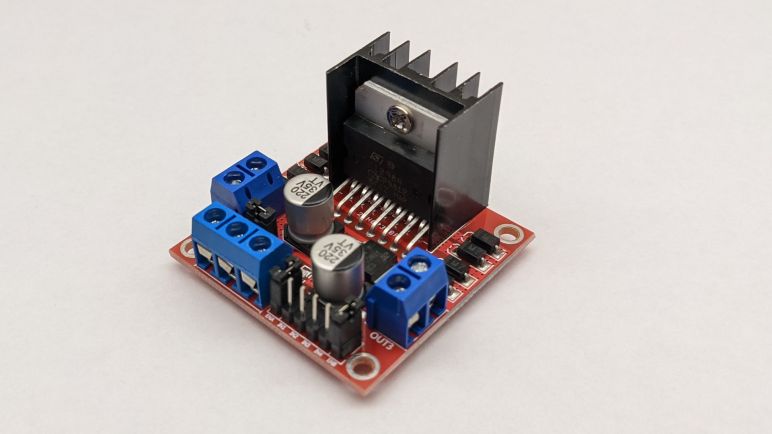
As a learning exercise, I decided to generate my own documentation for commodity L298N motor driver modules available wherever hobbyist electronics are sold. The first step was to catalogue all the components mounted on board, and now I analyze the circuit board layout to see how they are connected together. And as much as I like to do things digitally, for projects like this I really appreciate the flexibility and immediacy of a sheet of paper to scribble on.

I could probably do it with the actual device in hand and a blank sheet of paper, but this time around I decided to create my own visual guide. I took photos that are as directly square-on as I could front and back. I scaled them to the same size, and printed them side by side on a sheet of paper leaving room for me to write notes. Once printed, I folded the paper in half while holding it up to a light source so I could line up the front and the back. Then I started following copper traces and scribbling my notes.

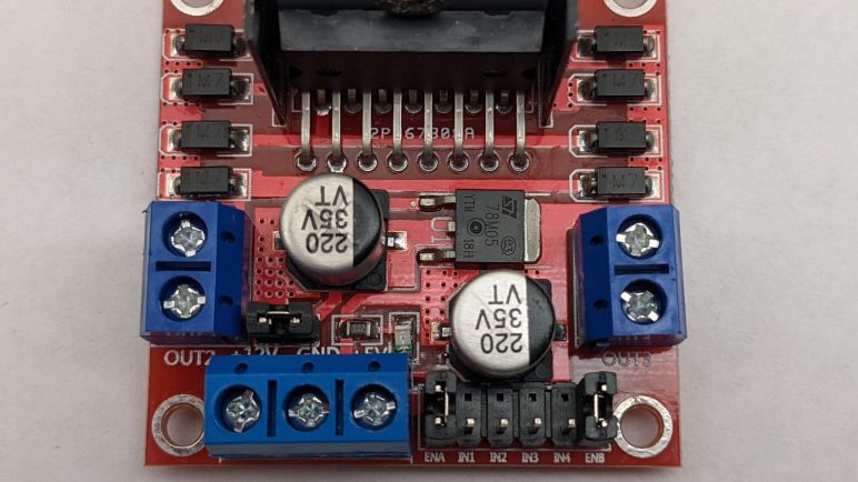
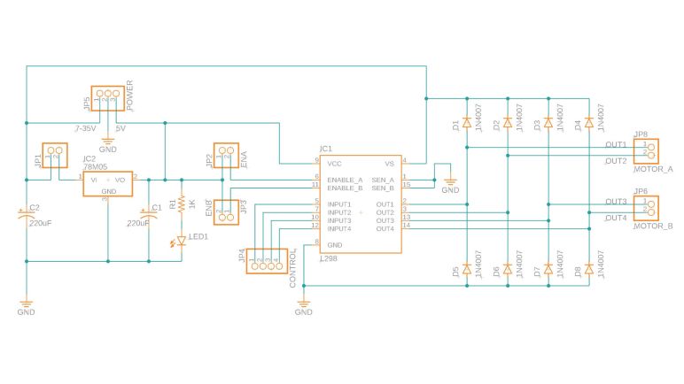
Fortunately this was a relatively simple circuit that mostly followed data sheet recommendations. I quickly confirmed the eight diodes were present to dump excess power into the +12V and GND planes. The two electrolytic capacitors are there for the +12V and +5V power planes respectively. IN1 through IN4 and OUT1 through OUT4 are straightforward direct routes. I also confirmed the optional current sensing resistors were absent, those pins were tied directly to ground. Furthermore, there was no provision to make adding current sensing resistors easy. People who want to perform current sensing are probably better off using another module.

A few traces were buried under components so their paths had to be teased out via probing with a continuity meter. The jumpers on ENA and ENB do indeed tie them high to the +5V power plane. The third jumper enable/disable the onboard 78M05 regulator. When the jumper is in place, it connects the +12V power plane to the input pin of 78M05. Which can then supply 500mA of current to +5V plane. Since the L298 itself draws less than 100mA, the remainder capacity can be tapped via the +5V screw terminal to perhaps drive a microcontroller. When the jumper is removed, regulator input is disconnected from the +12V plane and the +5V screw terminal becomes an input port to accept external power. The LED and current-limiting resistor is connected to the +5V plane and will illuminate when +5V power is present.

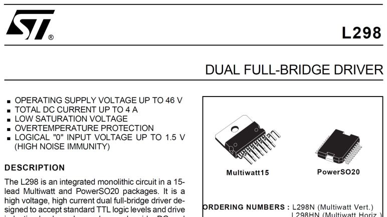
Aside from the silkscreened text proclaiming +12V, I found nothing to limit motor power supply to +12V. As far as I can tell it can be anywhere from 7 to 35V when using the onboard 78M05 regulator. If the regulator jumper is removed and L298N is running on external logic power, the lower limit is dictated by the L298N which can function with as low as 4V. The upper limit of a L298N is 45V with peaks of 50V, but the capacitors and 78M05 used on this module are listed with 35V maximums. Personally I’m unlikely to use anything higher than two 12V lead-acid batteries in series, which would be 28.8V fully charged and comfortably under that limit.

As a part of this self-assigned exercise, I also practiced drawing a schematic using the electronics design component of Autodesk Fusion 360. I think I’ve captured all of the information above, though I’m sure this schematic violates a bunch of conventions and make electronic engineer eyes twitch. (I’ve had to read software code written by electrical engineers so I have some idea what the mirror image is like.) And while I try to put lots of comments into my software source code, I haven’t learned how to best document a schematic. Until I learn more about that world, this blog post represents my best effort for this round.

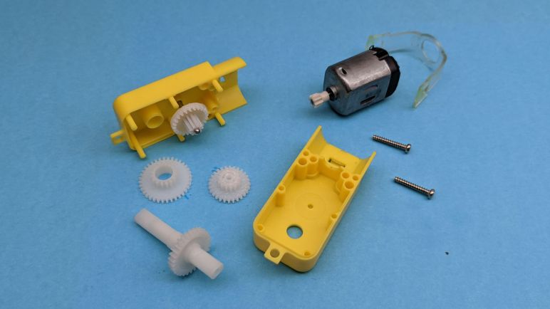
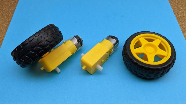
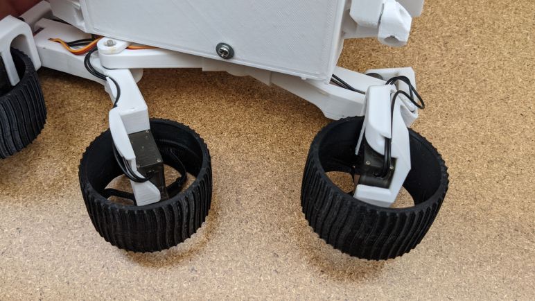
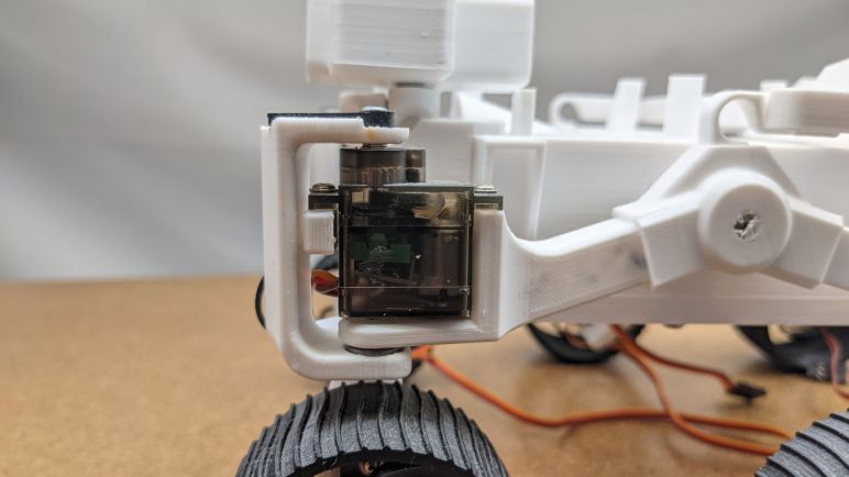
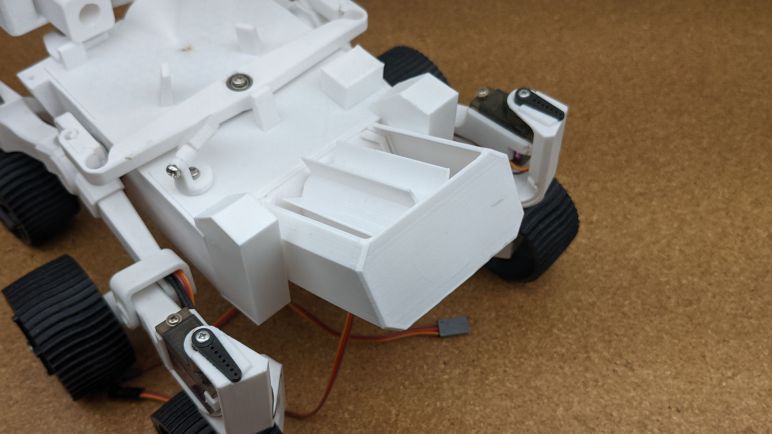
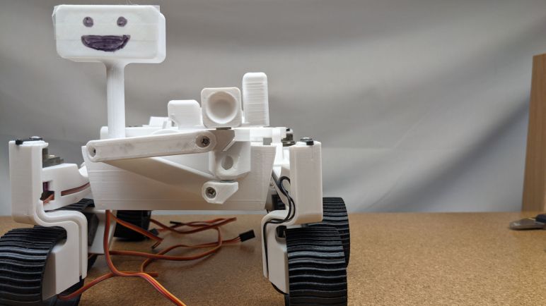
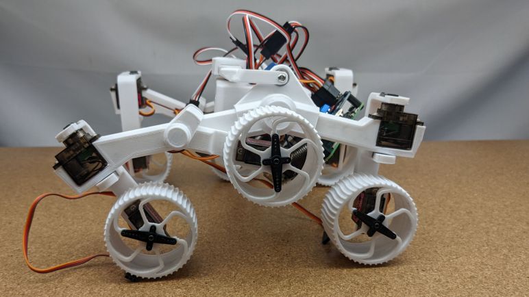
Armed with this knowledge, I felt confident enough to embark on designing a micro rover to use TT gearbox with its DC motor, leading to Micro Sawppy Beta 3.

Components of Generic L298N Motor Driver Module

The internet is a great resource, but sometimes I want the experience of doing something on my own. This is why after buying a batch of generic L298N motor driver modules, I decided to sit down and understand what I have on hand instead of just downloading someone else’s documentation.

The main attraction with the big heat sink is the L298 itself, specifically the L298N variant. Flanking it, four on each side, are small modules labelled “M7”. Since the datasheet said an array of four diodes each are required for A and B sides, seeing eight of something on the board makes them candidates for those diodes. A search for “M7 Diode” indicates they are 1N4007 diodes.

A single rectangular package is etched with ST logo and designation 78M05. Its datasheet describes it as a voltage regulator delivering 5V at nominal 500mA. Input voltage can be up to 35V, but must be at least 7V. Two cylindrical assemblies are likely electrolytic capacitors. The numbers indicate 220uF at up to 35V, matching the maximum limit of 78M05. L298 datasheet required a capacitor between motor voltage supply and ground, and another capacitor between logic voltage supply and ground, so that fits.

Two blue screw terminal blocks on either side are motor output connections. They are labeled OUT1 and OUT2 on one side and OUT3 and OUT4 on the other, designations straight from the L298N data sheet. Also straight from the data sheet are control signals IN1, IN2, IN3, and IN4. There are jumpers on ENA and ENB. My hypothesis is that they are tied to +5V to stay in the enabled state by default, allowing motor direction control going full speed forward, full speed reverse, and brake stop. If an application wants control over enabled state, we can remove jumpers and connect the enable lines for PWM speed control.

The third screw terminal block has three posts labeled +5V, GND, and +12V. GND is obvious enough, and given the presence of 78M05, my first guess is that the +5V terminal gives the option of tapping its output to drive our microcontroller. But it is also possible it is a +5V input to bypass the 78M05. There is a jumper nearby to disconnect something, possibly the 78M05? A small surface mount LED and accompanying current limiting resistor probably indicate power on one of the power rails. Finally the +12V label is mysterious, since everything I see with a voltage limit can go up to +35V and I see no reason to constrain it to +12V.

Looking over the list of expected components, I am left with two missing: there are no candidates for current sense resistors. Time to trace through this circuit and see if I can find them.

Trying Generic L298N Driver Board

I started researching using a L298 as motor driver because it is an established known quantity. After looking over its specifications, I realized it is not the best match for the TT gearbox DC motors I plan to use: the L298 is specified to work anywhere from 4 to 45 volts, but the little 130 DC motors used in a TT gearbox are usually listed with a nominal operating voltage of three to six volts. I should be able to avoid damaging the little motors as long as I keep the PWM duty cycle low. So I’ll continue investigation. Even if these aren’t the best drivers to use for my micro Sawppy, they might be useful for larger motors in larger Sawppy rovers.

During my research of L298 I came across reference to an Arduino motor control shield built around one of those drivers. It looks great, but a single shield with a single L298 can only drive two motors at different speeds. A six-wheel drive rover will have six motors. I could pair up front and back wheel motors if my rover chassis is front-back symmetric, but that still requires four different speed controls. I looked to see if the Arduino shield is stackable, but unfortunately the motor control pins are fixed so stacking them would only result in more motors running at the same two speeds.

Both Adafruit and Sparkfun appears to have moved beyond the classic L298 for their motor driver boards. I’ll look at those drivers modules later, for now I’m focusing on L298 so I headed to the cutthroat market of lowest-bidder generics, just as I looked there for my micro-servos and TT gear motors. A query for L298 on Amazon (*) returned many vendors all selling what looks like clones of the same product. A pattern repeated on AliExpress as well. I purchased from the Amazon lowest bidder du jour (*) for a closer look.

And just like with micro servos and TT gear motors, I couldn’t find much on the history of this particular driver module design. Somebody must have built and sold the first one, but now that it has since been copied infinitely I had no luck finding the source. Since this has become a generic fungible item, none of the vendors I checked bothered to supply documentation. They probably assumed a people can find it online somewhere and I’m sure I could. However, I’ve made a conscious decision not to. As an educational exercise I’ll try to decipher this module on my own.

Alrighty, what’s on this thing?


(*) Disclosure: As an Amazon Associate I earn from qualifying purchases.

Notes on L298 Dual Full-Bridge Driver

My little rover project switched away from modified servos with unpredictable motor drivers to pure DC gear motors. The good news is that this switch allows me to take control of the motor driver. The bad news is that… well, now I have to control motor drivers myself.

For this exploration, I’ll start with a classic the L298. These are featured in countless tutorials for turning digital logic into physical motion with motors and solenoids. It is not the latest technology, it is not compact, it is not efficient, but I expect L298 (or clones) to be available anywhere maker electronics are available. It’s such a classic that in the official ST Electronics datasheet PDF, diagrams are blurry as if scanned from paper instead of generated directly. At least the text is clear, but it is also amusingly dated “Jenuary 2000” so maybe we’re looking at a document with OCR-enhanced text (with OCR errors) and old scanned diagrams.

When used to control DC motors like my current project, a L298 is usually put to work running two motors. There are two sides “A” and “B” each with its own control signals and output pins, though both share common power supply and ground pins. Motor can be driven at up to 45V with occasional spikes are allowed up to 50V. Electrical current is up to 2A with occasional peaks of 3A. Steady state, that multiplies out to 45V * 2A * 2 motors = 180 Watts, a respectable chunk of power which explains why there is a big metal tab for heat dissipation and datasheet says operating temperature may rise to as high as 130°C.

The chip itself requires 5V input for internal logic, separate from the motor power supply. For digital logic purposes, anything under 1.5V is treated as logic low. This is relatively high threshold and is intentionally done to to mitigate electrical noise coming from motors next door. Fortunately that should not present problems for newer 3.3V microcontrollers like ESP32, Teensy and newer Arduinos. Data pins draw up to 100uA which shouldn’t be a problem to pair it with modern chips with far less amperage capacity than old school 8-bit chips.

Figure 6 explains how our microcontroller controls motor behavior. Direction is commanded by raising one input high and pulling other low. If they are equal, we get motor brake which we are warned must still not exceed 2A. If enable is low, the motor coasts independent of input values. Reading this chart, I understand that proportional motor speed control is accomplished by putting a PWM signal into the enable pin, alternating between applying power and coasting. However, I don’t see a recommendation on what my PWM frequency should be.

A web search found this electronics StackExchange answer that claims single-digit kilohertz would be sufficient. However, there’s also a contradiction in an answer that first claims PWM is done on the control input lines and enable is simply tied to high (always enable), but then links to the Arduino motor shield with L298N where the schematic clearly has PWM input lines going to the enable pins. Strange! I’ll follow Arduino precedent and send PWM control to the enable pin.

Another use for the enable pin is in the power up/down sequence. Enable pin should be pulled low before motor supply is turned on, and should be low before motor supply is turned off. Speaking of power, when driving inductive loads (and motors certainly are) a 4-diode network is required to dissipate power that might feed back to the circuit from these coils.

I saw several mentions of a current sensing resistor, and I see a “Rs” in all the schematics, but there’s no specification for resistance value or any other information beyond that they should be grounded as close to L298’s GND pin as possible. No reference for how L298 interprets current as a function of ohms resistance. Eventually I figured it out: the current sensing pin is only a provision for those that want to add a current sensing circuit to their design elsewhere. The L298 itself doesn’t care, and that’s why ohms are not specified in this datasheet. It’s going to be implementation-dependent so time for me to get my hands on an implementation.

TT Gear Motor Teardown

Commodity TT gearmotors became the center of my attention once I decided to switch to using DC motors for driving wheels on my little Sawppy rover project. Where did this form factor come from? Why do people call them TT? Why are most of them yellow? I don’t have answers to those historical questions, but I will see if I can build a little rover with them.

The adventure starts with buying a batch and taking one apart to see what’s inside. I’m not sure if the commodity TT gear motor market has diversified implementation like the micro servo market. If this experiment with TT motors go well, I expect I’ll buy more batches in the future for more little rovers and I’ll open those up to look for differences. Right now I could only speak to this one.

Externally, we see three mounting points. Two mounting holes go through the entire gearbox, next to the two screws holding the gearbox together. A third mounting hole is on a thin tab at the end opposite from the motor. There are two attachment points to the output shaft, which appears to be symmetric and have identical detent patterns. Turning the output shaft by hand, I can see the other output shaft moves in sync, but that doesn’t necessarily mean it is a single piece.

While the output shafts appear symmetric, the rest of the gearbox almost but not quite symmetric. The motor is offset by a little over a millimeter away from the camera in these pictures. On the side facing the camera, we see a little nub above the axle, whereas its opposite side is smooth.

The motor is held in place by a band of clear elastic plastic held by hooks molded into the gearbox exterior. In this particular unit, the clear plastic has partially melted into the yellow plastic and had to be peeled off with pliers before I could stretch them for removal. Once the clear plastic is removed, the motor can slide out. (To release just the motor, it is not necessary to remove the two screws seen in this picture.)

The motor looks very much like a commodity form factor used in many battery-powered toys. In disassembly and hacking circles I frequently see it referred to as “Mabuchi motor”. But just like “JST connector” this is not precise enough. Mabuchi Motor Company has a large product line, most of which aren’t this thing. I found references to this sized motor as FA-130, but with such commoditization I’m certain the majority aren’t genuine Mabuchi products. There’s certainly no Mabuchi logo on this particular motor.

What’s important for the purposes of project creation is that this is a common form factor. And thanks to its use in products like the Tamiya Mini 4WD product line, we can get motors with a wide range of performance characteristics. Same external motor dimensions, but different tradeoffs for torque vs. max speed, etc. At least that’s the theory, I won’t know for sure until I try buying one of those Mini 4WD Hop-Up motors and try installing it in one of these gearboxes.

With the two screws removed, I could open up the gear box and see the gears inside. Pulling the gear train apart, I find four separate components.

My first observation is that all the gears appear to have different diameters. I’ve seen a few TT gearbox modding guides that claim I could select different gear ratios by flipping some gears around, but I don’t see how that is possible when the gears are all different diameters. I’m either overlooking something, or this unit is the wrong variant for that mod to work.

My second observation is that the output shafts poking out on both sides of the gearbox are indeed part of a single piece shaft. There are no ball bearings here but at least they are supported on both sides of the shaft. However, since the output shaft is very clearly asymmetric, I should pay attention to which side is used as the main weight bearing member. Looking at this teardown, I have a clear preference for the side further from the camera in these pictures. That side of the shaft has far more support, in the form of a plastic tube approximately 8mm long. The side closer to the camera (and laid flat against the surface in these pictures) has only a thin wall of plastic for support.

I wonder if there’s a situation where the opposite is true? Perhaps when torque is a concern and we want to be closer to the final output gear, in order to minimize torque imposed on the shaft? I don’t think that’s likely at this power level, but I’ll keep an eye open for the possibility.

I didn’t need to take apart this DC gearmotor to use it, but having seen its insides I feel more confident approaching the task of mechanically adapting it to rover duty. In the meantime, I have a parallel adventure of learning how to drive these motors electrically.

Notes on TT Gear Motor

I’m now looking at DC motor with gearbox for rover locomotion. I started my little rover project with the intention of using micro servos all around. For six wheel drive, they would be modified for continuous rotation. This is a tradeoff: we gain a servo’s existing H-bridge circuit with proportional control, but we take the risk of putting a physical load it is not designed for. Unfortunately I found a problem with my Beta 2 chassis: some of these inexpensive micro servos lack useful proportional control. If I can’t depend on a servo’s existing circuitry, I might as well switch to a different gear motor: the TT gear motor.

Similar to micro servos, the TT gear motor has become a commodity item. Made by lots of manufacturers and sold by lots of vendors. (*) Where did this design start, why is it called “TT”, and why are they all yellow? Sadly I found no satisfying answers to these historical questions. Searching on the internet was made difficult by their name, which tends to return results relating to a real car, the Audi TT. Did this gearmotor start life in a toy car modeled after the Audi TT? So many questions, so few answers.

The only bit of information I found hinting at a source was a mention on the product page for Solarbotics Gear Motor 3 which superficially resembles the TT gearbox. However, it is not called TT there, and it is not yellow, so clearly this is not the entire history.

Based on the original design by Mark Tilden for use in the B.I.O.Bugs & RoboSapien, these motors are the next generation with a variety of improvements such as dual output shafts and a lower current motor.

Product Description for Solarbotics Gear Motor 3

I found no corroborating information beyond that snippet of text.

Anyway, back to the device itself: we can see it uses a much larger motor than the one inside a micro-servo, which may be (but not necessarily) more powerful. A larger gearbox also implies larger and more durable gears. But the most important part is that these are used to drive the wheels in a robot kit. For example, Servo City’s Runt Rover series use this type of motor for their wheels, albeit in black instead of yellow. The fact they are designed for wheels makes me more comfortable I’m using mechanical parts for their designed task. Which was a worry for (mis)using continuous rotation micro servos for micro Sawppy beta 1 and 2 rover wheels.

And thanks to the popularity of this form factor, we have an ecosystem of variants in the same size and fit the same axle. The standard gear ratio is 1:48, but other gear ratios are offered for those who want to make different tradeoffs between speed and torque. High torque gearboxes need to more durable, but not to worry, this form factor with higher gear ratios are also available with all metal gears in products like Adafruit #3802.

A particular wheel design is most commonly associated with this gearbox, but there are alternate wheel choices to fit onto that axle. The axle is large and simple enough that we can probably FDM 3D print our own wheels as well. That output shaft is symmetric so some robot kits put two wheels, one on either side. But I usually see the other end either left unused or used for an encoder wheel for low resolution wheel odometry. (*) If we want higher resolution encoders, we can buy variants with an encoder on the motor.

This all looks very promising so I bought some TT gearmotors for experimentation. First order of business: take one apart to see what I’m working with.


(*) Disclosure: As an Amazon Associate I earn from qualifying purchases.

DC Gearmotors For Little Sawppy Rover

Based on my experience modifying wheel drive motors on my little rover Micro Sawppy Beta 2 (MSB2), I decided it was trending towards a rover design that would be too difficult to work on. If I, as the designer of MSB2, am tearing my hair out struggling with wire routing, how can I realistically expect beginners to work with this thing? I think MSB2 succeeded at being really cute, unfortunately the beauty was only skin deep and its core difficulties are not what I want.

But while I stopped further work on MSB2, I wanted to continue the task I was in the middle of: trying out the idea of using DC gearmotors. The micro-servos I used in MSB2 taught me that my original idea for driving little rover wheels were unreliable. While we could modify micro servos for continuous rotation, there’s no guarantee their control circuits would give us usable speed control. Sometimes they don’t! In order to guarantee a little Sawppy rover could be reliably built, I must take motor speed control into my own hands.

This decision started when I removed all electronics from MSB2 wheel servos, using them as just a motor with a gearbox inside a micro-servo sized enclosure. (FYI Adafruit product #2941 is exactly like this, no modification required.) Even though I’m throwing out half the device, it’s still a very inexpensive way to obtain a small DC gearmotor thanks to the large volume market of generic commodity micro servos. But if we are going to use a small high volume commodity DC gearmotor to drive little rover wheels, there’s actually a better option: TT gear motors.

These DC motor + gearbox units are ubiquitous like generic micro servos, mass produced by many manufacturers at high volume and low cost. It is available as Adafruit #3777 but they are definitely not the only retailers. (*) I first learned they existed when I saw them pop up in multiple projects submitted to a Hackaday contest, and a little background research unveiled how widespread they were.

Since I’ve decided to add the complexity of DC motor driver modules, these TT motors immediately jump to the top of the list. Unlike micro servos, TT gear motors were designed for driving wheels.


(*) Disclosure: As an Amazon Associate I earn from qualifying purchases.

Micro Sawppy Beta 2 Wire Channels Are Too Hard To Work With

My little rover project Micro Sawppy Beta 2 (MSB2) turned out to have (effectively) three speeds: stopped, full speed forward, and full speed reverse. MSB2 originally intended to get its six-wheel drive from inexpensive micro servos modified for continuous rotation. This approached worked for its predecessor MSB1, but MSB2 used servos from a different manufacturer and their feedback control circuit had very poor (or poorly tuned, or nonexistent) proportional control. As a result it was nearly impossible to drive MSB2 at partial throttle.

Given this setback opportunity to try other ideas, I started modifying all six wheel drive servos. I unsoldered the flawed control circuit board and soldered wires directly to the motor input terminals, intending to route those wires to a motor control H-bridge circuit of my own choosing. This would mean I’m only using the mechanical portions of the micro servos, effectively turning it into a DC gearmotor.

But I only got halfway. Unsoldering the board and soldering motor wires is well within my comfort zone, but wrangling with wires got very tedious and frustrating. In order to replace the three-wire continuous rotation servo wires with two-wire motor control, I have to struggle with the intricate wiring channels I’ve designed into suspension components. In fact I have to struggle with it twice: once to remove the wire, and once to add the replacement.

That’s when I realized MSB2 has failed some very important project objectives: making the rover easy to build, easy to diagnose, and easy to repair. For the three wheels I managed to convert, it took far more time to wrestle with the wires than it did to perform soldering, and that’s just wrong. I want a design where, if a servo dies, it can be quickly replaced to get the rover back up and running. The wiring channels may give us a tidy looking rover, but not one easy to work with. As a result I’ve decided MSB2 is going down the wrong path and stopped work on this iteration. But I am thankful for the cute little rover, it taught me the tradeoff for tidy wiring and gave me motivation to examine using DC gear motors to drive a little rover’s wheels.

Micro Sawppy Beta 2: The Runaway Rover

Once I built up my little rover Micro Sawppy Beta 2 (MSB2) I observed that its steering servos were acting differently from the batch I used for MSB1. Beyond the clearly visible physical differences, these servos also had different control logic that can get into a never-ending oscillation.

A contributing factor here (if not the main factor) is that this micro servo’s motor control logic is far too eager in its corrections. It applies too much power and, if that power is not absorbed by damping, we have over-correction which repeats the cycle. In theory the motor controller uses power in proportion to the error in position. If the target position is close, it should use less power than if the target was far away. This particular servo control board has poor (or at least poorly tuned) proportion control. It seems to use the same amount of power whether the target position is close or far away.

The occasional oscillation is moderately annoying for rover steering, but at least it is usually damped out when the rover is sitting on its wheels. I didn’t experience the full impact of control algorithm used in these micro servos until I converted them to continuous rotation for rover’s six wheel drive. Now the poor proportional response manifests in a rover that I can’t run at partial power. I could make MSB1 crawl slowly up obstacles, but MSB2 didn’t want to crawl slowly like a real Mars rover would. It is either stopped or booking across the landscape at full speed.

In this scenario I suppose I could also apply damping by increasing the workload. Which means either adding friction to the drivetrain or making the rover heavier. This is assuming the motor will exhibit proportional behavior at higher load levels, which is possible but not yet proven. But despite the light weight causing other problems, I didn’t like the idea of adding friction or weight purely for the sake of ballast. So I am going to explore a different venue by removing the flawed servo control board. I’ll have to find some other motor controller and use only the mechanical portions of these micro servos as a DC gearmotor assembly.

Micro Sawppy Beta 2 Has The Shakes

The robot arm I built as a test mockup for my little rover Micro Sawppy Beta 2 (MSB2) was a simple manually-posed affair. I wanted to get a better feel of how such a thing would articulate before I put in the work to motorize it, and I had no suitable actuators on hand anyway. In fact, I had no idea what I would use for such a project, since I found problems with the micro servos I’m already using in this project.

There are a few robot arm designs built around the same small affordable micro servos. For example, the MeArm is a super minimalist robot arm designed to be assembled from laser-cut pieces. I’ve seen a few MeArm in person and based on how they moved, I could tell there are some challenges to use them effectively. One problem I witnessed was that, under certain circumstances, a particular servo would get into an oscillation bouncing on either side of the target position. Unable to ever reach that position and hold it steadily.

I built and ran MSB1 without seeing such behavior and had been feeling pretty good about things, but MSB2 used a different batch of micro servos from a different manufacturer. With this batch, I saw the same oscillation I saw on a few MeArm affecting MSB2 steering and I think it’s coming from certain servo control boards. Or at least I don’t see how it could be caused by my mechanical design changes between MSB1 and MSB2.

The comments on my tweet support my hypothesis: this batch of micro servos have some shortcomings in its feedback control logic to cause this behavior. I think it is very likely a deliberate engineering tradeoff decision dropping some feature to make it cheaper, given that these micro servos were built to minimize cost. There were multiple suggestions to add damping which does indeed mitigate the problem. For MSB2, this oscillation only occurs when I hold the steering mechanism up in the air. Once I set down the wheel, friction between wheel and ground adds enough damping to stop the oscillation.

I’m feeling particularly irritated at this servo behavior, because it turned my beloved feature into a bug: the smooth low friction rotation enabled by ball bearings is a contributing factor for this oscillation. If I didn’t use ball bearings and had high friction steering, this oscillation would probably not happen. But annoying as this was for steering, it became a disaster for driving.

Micro Sawppy Beta 2 Robot Arm

My little rover Micro Sawppy Beta 2 (MSB2) has a mock RTG in the back, and in the front I installed a mockup for a rover robot arm. Even as a non-motorized mockup, it was more than Sawppy V1 ever got! A Sawppy arm was always on the to-do list but I never dedicated the time to make it happen. In the absence of my own efforts, I’m happy to see some other Sawppy builders have added robot arms to their rovers. Like CJ’s arm documented here on Hackaday.io and on YouTube.

And this rover flexing its arm on Twitter.

Both of these robot arm projects followed the mechanical geometry of real Mars rover arms, which makes me happy in a “These are my kind of people!” kind of way. I haven’t studied the arm as much as these other Sawppy builders had, so I decided to start simple and small with MSB2. I designed and printed a very simple arm as practice. I didn’t have any kind of actuators on hand that would work at such a small scale, so this arm is limited to manual articulation. (I could pose it like an action figure, but no remote control or autonomy.)

Still, it was instructive to see what kind of motion is possible with this mechanism. I knew two things from the start: it needed to go into the stowed position and it needed to extend out to act like it is retrieving a Mars sample. Once I started playing with it, though, I learned two other things.

The first lesson is that this draft had only a subset of range of motion as the real thing. I couldn’t replicate the sample storage movement sequence shown in a NASA tweet illustrating how Perseverance will transfer core samples to the carousel handling tools and sample tubes. The second lesson is that I had a vague idea to build a rover that can be friendly and wave “Hi” to people, but this arm could not bend the way I wanted because it would collide with the left front wheel steering servo. I’m glad I learned these lessons on a simple test arm, before I spent the effort to motorize my arm. What I could use for arm actuator is a problem itself, as I encountered a problem with the micro-servos I’ve been using.

Micro Sawppy Beta 2 RTG Power

The equipment bay for my little rover Micro Sawppy Beta 2 (MSB2) had enough space for the temporary setup of Raspberry Pi 3 and Adafruit PWM/Servo HAT along with all wires and a battery. However, I’m trying to think ahead to more elaborate setups and how I might accommodate their needs. One obvious concern is that bigger computers would need more space and bigger batteries, both competing for room inside the equipment bay.

Mars rover engineers at JPL had already encountered this problem and we can see their solution: Curiosity and Perseverance draw their electrical power from a radioisotope thermoelectric generator (RTG). Unlike their predecessors, who drew electrical power from solar panels that imposed a lot of operational limitations. Mars-bound RTG are large and bulky devices bolted prominently to the rear of those two rovers, giving them a very distinctive rump. Since MSB2 tries to look like the big rovers, it will also have a similar-looking attachment to the back, so we might as well make it serve the same purpose! (And to be clear I meant power supply, not a radioactive generator.)

Since MSB2 could fit its battery inside the main body, I didn’t need to make this faux RTG functional just yet. For MSB2 it is only a test run mockup without any paths for power wiring. I found that if I made it according to proper scale, the mock RTG would be (just barely) large enough to accommodate a single 18650 lithium-ion cell. It also looks pretty easy to make the chamber easily accessible, so the battery could be swapped out.

But with that success, my ambition grew: what if I could find a little more room? I could accommodate a USB power bank built around a single 18650 cell. If micro Sawppy could be built to run off a commodity USB power bank, that would make it a lot more beginner friendly. First, the construction would be simpler and second, beginners would be spared the learning curve of working directly with infamously temperamental lithium ion battery cells.

So that’s another research project: what are the power requirements for a micro rover, and would it fit within the power delivery capabilities of a USB power bank? I know this specific USB power bank in my picture doesn’t have the grunt to keep a Pi 3 running, so it is another motivation to scale down from the current electronics configuration to make room in the power budget for other component like a robot arm.

Micro Sawppy Beta 2 Equipment Bay

My little rover prototype Micro Sawppy Beta 2 (MSB2) had a few suspension changes relative to its predecessor MSB1, but the real attraction is the rover body. Whereas MSB1 had a minimalist box, MSB2 makes an effort to look like Mars rover Perseverance.

The minimalist box of MSB1 is, in fact, a little too minimalist. I thought I made it large enough to accommodate a Raspberry Pi 3 and Adafruit PWM/Servo HAT but I made some mistakes and it was too small, leaving its brain dangling outside the body by wires. Not exactly a robust approach. MSB2 has a much larger body with a correspondingly larger enclosed equipment bay for electronics.

The major structural points of a Curiosity/Perseverance-like rover are where the differential pivot attaches plus the two rocker attachment points. These three attachment points carry the entire weight of the rover so I wanted it to be a strong single piece, but printing it as one piece added a lot of complication elsewhere. MSB2 body was printed upside down so they could be together, but that meant I couldn’t print a bottom since it would be an unsupported top surface while printing. And while I could theoretically seal off the top of the box (since it’s bottom and facing the print bed when printed upside down) I didn’t want to do so for two reasons: One, I wanted to print some surface features to resemble Perseverance, and I couldn’t do that if it’s flat against the print bed. And second, I wanted the equipment bay to be accessible while the rover is standing on its wheels right side up. With all these conflicting desires, the main body box ended up with too many separate pieces. I plan to play with other ideas in future iterations, the next thing I’ll try is to abandon the desire to print all three structural attachment points with a single piece. At this scale, a few M3 fasteners are strong enough to hold things together.

One thing I did like about this box was the volume, which is modest but enough for a Raspberry Pi and Adafruit HAT. I have ambition to build smaller and/or simpler electronics for future iterations of micro Sawppy, but those plans have not yet solidified. I think leaving enough room for Pi and a hat leaves a good upgrade path, but there’s always a question of how much to plan for upgrades. I think it’ll fit some Ardupilot control units, but I don’t know for sure since I lack experience with them. This body is definitely not big enough for something like an Intel NUC, though perhaps it’s enough for a Jetson Nano. However, the sealed box would present cooling challenges for those power-hungry devices, in addition to their need for big batteries.

Micro Sawppy Beta 2 Differential Link

My little rover prototype Micro Sawppy Beta 2 (MSB2) has a few suspension changes relative to MSB1. The change to its differential linkage system is not as significant as the changes to steering mechanism, more of a small evolution.

While driving MSB1 around I watched the linkage move and thought it was worth an experiment to see if I could eliminate all the metal components. (Bearing and associated screw and nut.) The linkages became two 3D-printed living hinges that are designed to flex on axis perpendicular to each other. Ideally it would allow each hinge to accommodate most of motion along one axis letting the other one handle the rest. In practice this only partially worked and the hinges were too stiff. The loads didn’t distribute as nicely as I had imagined in my head. Real world is like that sometimes! (Actually most of the time, if I’m being honest.) The end result is that these differential link hinges hindered weight distribution mechanism of the rocker-bogie suspension.

I could make these hinges more flexible by printing thinner plastic, but then we increase risk of fatigue and breakage. PETG is more ductile and durable than PLA, but neither of them are close to properties of dedicated flexible filament. Not all printers can handle TPU or similar materials, and I want to design my rovers to be printable even on cheap basic printers that only handle PLA.

The potential for breakage highlights another problem with tightly integrated designs: if the living hinge breaks, the entire component has to be reprinted. I’m still undecided about using 3D-printed living hinges, so there will be a few more rounds of experimentation to gather more data. But if I want to use living hinges printed from plastic filament not intended to be flexible, I should at least change the design to be a multi-piece part. If the living hinge itself is a smaller separate component, it can be reprinted quickly for replacement in case of breakage. Which I don’t think is a huge risk when rolling around, but unintentional sharp jolts happen a lot when I am trying to open up this rover’s equipment bay.

Micro Sawppy Beta 2 Steering

Most of the focus for Micro Sawppy Beta 2 (MSB2) is on building a body that resembles real Mars rovers, so its miniaturized rocker-bogie suspension is largely unchanged relative to MSB1, inheriting all the same flaws. The most notable suspension changes are in how its steering servos are installed.

Relative to MSB1, steering servo body is flipped around front-back so the bulk of the servo body faces away from the steering knuckle. The upside is that it allows that bracket to be narrower thus saving space. The downside is that wire routing becomes more convoluted as the wires jut out away from the body and have to double back. It “wastes” some wire length but that has minimal impact, as I’ve determined I had to use servo extension cables anyway.

The other change is that the top half of the bracket is no longer in line (when viewed from the top) with the bottom half housing wheel driving servo, it has been rotated 90 degrees to be in line with wheel travel direction. This approach has several benefits, starting from a cleaner look when the rover is traveling straight ahead. It also increases the steering angle range, giving the bracket more distance before it would make contact with a suspension arm. This change, combined with the fact it is now narrower to begin with, allows much more room for the robot arm.

But there are a few downsides. Since it was printed 45 degrees relative to the 3D print bed, this design doesn’t enjoy the strength offered by a design aligned with print layers. To compensate for this, I made the bracket thicker in high-stress areas, but it still suffered breaks along layer lines in ways that the previous design would not.

Another downside is that it further compromised ground clearance, increasing the chances this plastic might impact obstacles on the ground. I think it’s still acceptable in light of modifications other have made to Sawppy V1, but it is definitely a step backwards.

The lesson I learned from this experiment is: while an one-piece design would satisfy the goals of reducing parts count, it is hard to satisfy all objectives and still remain in one piece. The thicker yet still more breakable bracket made it more difficult to assemble, which also made it harder to diagnose problems and repair them. And neither of these single piece designs allowed manual steering trim adjustment, which is a feature on my wish list.

In light of these experimental results, for the next version of micro rover steering mechanism I will go to a multi-piece design. I also decided to go multi-piece on differential link but for slightly different reasons.

Micro Sawppy Beta 2

The main objective of MSB1 was to establish that a scaled-down rocker-bogie suspension system could nominally function and expose problems along the way. That objective did not require much of a rover body, so MSB1 only had a minimalist “Scarecrow” box. The main objective of MSB2 was to build upon its established suspension system and add a body with some resemblance to Mars rovers Curiosity and Perseverance.

On top of that body is not a realistic model of a rover camera array. Instead, it has a smiling face, which follows the precedence set by rover illustration JPL used for Mars 2020 “Name the Rover” contest (resulting in Perseverance) and that of ESA’s ExoMy rover. I had contemplated various ideas on how the face can change, maybe small OLED panels or an e-ink display. For this first trial I just drew a face with black marker. (There was also a layer of cellophane tape to block marker ink from capillary action.) I did this during a virtual meet of makers and I was surprised that a simply drawn smiling face made a hugely positive difference on how people perceived my little rover project. Though I probably shouldn’t be surprised: there was a similar change in perception when I added googly eyes to Sawppy V1 after seeing it done by another Sawppy builder. A tiny change makes people smile.

For electromechanical actuation, MSB2 used MG90S metal gear servos from a different manufacturer so I can compare how they perform against the ones used in MSB1. This particular batch were the MG90S that had a mild case of false advertising: only the final output gear was metal (visible as silvery metal) and the remainder were all black plastic. The two batches were bought from the same Amazon vendor on the same product page (*) but they are obviously distinctly different products. One of the differences had a serious impact on MSB2 and changed the direction of the project, more details in a future post.

I originally intended for MSB2 to be up and running in time for launch of Perseverance rover, but as is usually the case, other things happened. All I could do was a short video where I manually moved MSB2’s poseable arm waving a flag cheering Perseverance on. But it became a part of JPL’s official launch tweet, and I’m quite happy with that accomplishment even as I work through MSB2 design problems.


(*) Disclosure: As an Amazon Associate I earn from qualifying purchases.

Micro Sawppy Beta 1 Kicking Up Its Middle Wheels

Modifying Micro Sawppy Beta 1 (MSB1) suspension geometry to be front-back symmetric didn’t seem to cause any problems. Or at least, it didn’t seem to add any new ones. One trait I observed while running my little rover around is a tendency to kick up its middle wheel. When MSB1 encounters an obstacle it cannot climb, the front wheel stops moving but the rear wheel tries to push forward. As a result the suspension folds up, lifting the middle wheel. This is something that can be traced back to features inherited from big rovers.

Here are two side views for comparison between MSB1 and Curiosity rover. In an effort to draw up a cute little baby rover, I compressed overall length (front-back distance). This gives us a stubby little rover, but it also meant the rear wheel now has better leverage for lifting up the middle wheel.

I see this behavior occasionally on Sawppy V1, but not as frequently. Part of this is because Sawppy V1 proportions are faithful to Curiosity proportions and not squashed for cuteness, but also because of its heavier weight. In order to lift the middle wheel, we also need to lift a portion of the rover’s weight, and MSB1 is proportionally far lighter.

This lighter weight is a natural property of all scale models. MSB1 is roughly 1/3 scale of Sawppy V1, meaning it is about 1/3 as long. Which means it occupies about 1/9 the floor space, and occupies roughly 1/27 of the volume. All else being equal (they weren’t, but just for the sake of this simplified explanation) we would expect MSB1 to weight about 1/27 as much as Sawppy V1, making wheel lifts much more likely.

This propensity to lift a wheel is puzzling when we look at the forces involved and notice what happens when the rover is traveling backwards: If it encounters an obstacle it cannot climb, the rear wheel stops and the middle wheel will try to push backwards. In this case, the push will help lift the rear wheel so it could climb the obstacle, making the wheel lift a feature and not a bug. I was able to experimentally verify this property with MSB1: it climbs better running backwards than forwards.

Why would JPL engineers design a Mars rover that has superior climbing ability traversing backwards than forwards? It makes sense when we consider the operating environment: there are no roads or roadside assistance on Mars. Curiosity is designed so that it can back out of whatever situation it might get into, because the nearest tow truck is over 54 million kilometers away.

But this means we have to make a decision for little rovers running on earth, where we have the option to walk over and pick it up if it gets stuck. Do we flip around the suspension geometry so it climbs better? Or do we maintain geometry faithful to Mars rovers? For Sawppy V1 I chose to copy Curiosity, but I might need to take the other path for Micro Sawppy rover given its shorter limbs and light weight. That’s a decision I haven’t made for MSB2 but if I do so in the future at least I have precedent. JPL’s own Open Source Rover has its bogies up front instead of back.

Micro Sawppy Beta 1 Symmetric Front-Back Wheel Spacing

While working on wiring I remembered a design decision I made for Micro Sawppy Beta 1 (MSB1). One of the features that surprised me about Curiosity rover were its wheel spacing. With a casual glance at the rover layout, I saw three wheels on each side and assumed they were evenly spaced, but once I studied them in more detail I learned they were not. The two bogie wheels are slightly closer together than the distance between middle wheel and front wheel. I’m sure this represented the best tradeoff between many factors I’m ignorant of, but I have no idea what they might have been. I don’t even know what words to use to search for papers that might have been published to explain it.

What I do know is that their different distances meant each corner wheel had different results for calculating their Ackermann steering angles. When traveling in an arc, this results in four different steering angles and different wheel rotational velocities for all six wheels. This calculation itself isn’t a big deal right now. Since such math is pretty trivial for hardware platform like Sawppy’s Raspberry Pi 3, and executing different steering angles and wheel rotations is similarly easy with LX-16A serial bus servos.

But my goal is to make a rover that is smaller and simpler, and a part of that is willingness to deviate from Curiosity’s proportions. So I made this rover’s wheel spacing front-back symmetric. The middle wheel is now set equidistant from front and rear wheels. Now steering angle and wheel velocity only has to be calculated once for each side. The front and rear corners wheels on the same side would steer to the same angle (just opposite directions) and those two wheels would roll at the same speed.

Halving the math has little impact for MSB1, as its Raspberry Pi 3 had so much computing power to spare. And since it used the Adafruit PWM/Servo HAT for control, there were no reduction in complexity for electronics either. But MSB1 proved this approach can function, and is not the biggest problem with MSB1 suspension geometry. And once proven, it opens up possibilities for future simplifications. Allowing future rovers to use software and electronics that are less capable than what is on board MSB1.

Micro Sawppy Beta 1 Wiring

The electronics components I had used to get Micro Sawppy Beta 1 (MSB1) up and running are not representative of my final ambitions. It has a Raspberry Pi 3 with microSD card, the Adafruit PWM/Servo HAT plus two MP1584 buck converters. The upside of this system is simplicity of assembly: thanks to Adafruit, their HAT is close to plug-and-play with a Pi. And if someone uses another power solution, they might not need to solder those MP1584 converters. The servos, for example, could have been powered by a 4- or 5-pack of AA batteries.

The downside is that a remote-control toy rover is really only using a tiny fraction of the capabilities of this system, and these tasks can be done with something simpler and less expensive. For Sawppy V1 I wanted to leave headroom for explorations into autonomy, but it’s been a lot of fun even without that. So I’m OK with downsizing for a micro Sawppy as long as there’s an upgrade path. Whether it be Raspberry Pi, Ardupilot, or some other advanced controller. I still want to make micro Sawppy more affordable, but it’ll be a balance between low cost against ease of assembly.

For wiring, I followed ExoMy’s lead and designed in a lot of wiring channels in the suspension arms, trying to keep wires tidy and out of sight all the way until they pass through narrow channels into the body. Not all of these efforts worked. Some channels were too narrow, making installation impossible. Some channels were too wide, and wires fell out. This was disappointing, but also completely expected. I’m learning how to design wire management channels, I wouldn’t get it all right the first time.

But these intricate pathways had another impact: these micro servos are built with approximately 25cm of wire (plus or minus a few centimeters) which would have been long enough for a little rover whose overall length is about the same. However, now that they have to wind their way back and forth inside suspension components, 25cm is no longer enough.

I had a similar problem with Sawppy V1, where the wires that came with LX-16A serial bus servos were not long enough for a rover. I cut those wires apart and spliced them into a custom wiring harness, but I’d like to avoid that kind of electrical work for building a little Sawppy. Fortunately, unlike LX-16As, micro servos use commodity remote control hobby servo plugs. Which means I could use commodity servo extension cables. (*) And no wire cutting or soldering iron would be required to make MSB1 wires fit inside its suspension geometry.


(*) Disclosure: As an Amazon Associate I earn from qualifying purchases.

Micro Sawppy Beta 1 Electronics

The past several posts have described various aspects of Micro Sawppy Beta 1 (MSB1) that are explorations of new ideas for a little rover. Since there were already many new ideas piled onto the little guy, I decided the control electronics and software should step back and reuse known quantities. Even though I don’t intend this to be the final approach, I wanted to reuse existing components here just to keep things from going too wild and confused if the little rover should encounter problems.

Hence the onboard electronics of MSB1 is very close to those used on Sawppy, which was in turn adapted from code written for SGVHAK Rover. Not from the official JPL Open Source Rover instructions, but the hack I hastily slammed together for its world premier at Southern California Linux Expo. Back then we faced the problem of a broken steering gearbox a week ahead of the event, and it would take over a week for replacements to arrive. So while Emily hacked up a way for a full-sized RC servo to handle steering, I hacked up the rover software to add option to control a servo via what I had on hand: the Adafruit PWM/Servo HAT.

Years later, I still have that same HAT on hand and now I have a rover full of micro servos. Putting them together was an obvious thing to try. My software for that servo steering hack turned out to be very easy to adapt for continuous rotation servos powering the wheels. (Only a single bug had to be fixed.)

There was another happy accident: since the SGVHAK rover software already had software provisions for steering trim, it was easy to use that for throttle trim as well. This was useful to compensate for the fact that the converted continuous rotation servos in the six wheels aren’t necessarily centered like they theoretically were. Resistors with identical markings don’t actually offer perfectly equal resistance, and the control circuit of a cheap micro servo isn’t very good about precise voltage measurements anyway. If I didn’t have this software throttle trim control, it might have been much more difficult to get MSB1 up and running.

For power supply I had a small 2-cell Lithium Polymer battery on hand, previously seen on these pages in exploration of a thrift store Neato. Dropping its voltage (8.4V when fully charged) down to something that wouldn’t fry the micro servos was the job of MP1584 buck converters. I had discovered these worked well for powering a Raspberry Pi and one of them is again enlisted into that role. In order to reduce the chances of a power sag causing the Raspberry Pi to reset, I added a second buck converter to give the micro servos an independent power plane. Both buck converters are soldered onto the little prototyping area Adafruit provided on their HAT. Once I had the electronics circuit stack assembled, I could start wiring up all the components.